Continue to Site

Welcome to EDAboard.com

Welcome to our site! EDAboard.com is an international Electronics Discussion Forum focused on EDA software, circuits, schematics, books, theory, papers, asic, pld, 8051, DSP, Network, RF, Analog Design, PCB, Service Manuals... and a whole lot more! To participate you need to register. Registration is free. Click here to register now.

Flags, interrputs and bit registers for 8052

Status
Not open for further replies.

m8052

Newbie level 3
Newbie level 3
Joined
Jun 8, 2013
Messages
4
Helped
0
Reputation
0
Reaction score
0
Trophy points
1
Visit site
Activity points
34
Hi there,

I am having hard time understanding a couple of codes below. These are written for 8052 AT89S52 microcontroller.

The only thing I know about these is that they are specific bit registers...

Code:
bit update_flag=0x10; 
bit zv_flag=0x12; /* ZV_flag here*/
bit zc_flag=0x12;  /* ZC_flag here*/
bit lead_flag=0x12;  /* LEAD_flag here*/
bit lag_flag=0x14;   /* LAG_flag here*/

bit time_possibilities=0x11;

If you could please explain it a bit more what their purpose is, that would be great! Thanks.

Another question is if I am using external interrupts INT1 AND INT0, do I need to use different timer for these?

For examle,

Code:
void int0_ZVS(void) interrupt 0

{
if (lag_flag==1)
/* If lag_flag is enabled, reset the timer and set the timer */
{

TMOD|=0x10; /* Initialisation of Timer1 16 bit Timer */
TH1=0x00; /* Reset high value of the timer1 */
TL1;0x00; /* Reset low value of the timer1 */
TR1=1; /* Set the timer1 */
zv_flag=1; /* Set zv_flag */
}

after this, should I initialise the Timer 0 like this? is this the right thing to do?

Code:
void timer() /* Timer function */
{
/* Using built-in timers start.
Timers are needed to track the high and low point of the signals */
TMOD=0x01;  /* Setting the mode1 of Timer0 */
TH0=0x00; /* Set the timer for high */
TL0=0x00; /* Set the timer for low */
/* Using built-in timers end */
}
 

Hi friend,

I can able to help you. But I hate to say it. I confused on your 2nd question.
Why are you using timer for external interrupts?
In an 8051 micro controller there are 2 external interrupts, 2 timer interrupts, and 1 serial interrupt. External interrupts are – external interrupt 0(INT0) and external interrupt 1 (INT1).Timer interrupts are Timer 0 interrupt and Timer 1 interrupt. A serial interrupt is given for serial communication with the micro controller (transmit and receive) .

Regards,
 
  • Like
Reactions: m8052

    m8052

    Points: 2
    Helpful Answer Positive Rating
Thanks for your reply.
There is a comparator circuit one op amp goes to external interrupt 1, the other goes to interrupt 2.

1st op amp senses the voltage, the other one senses the current.

Microcontroller calculates the time difference between two.

Thats why i am asking if it is ok to use another timer inside the interrupt. For what purposes you can use timer inside interrupts?
 

Hi friend,

Please excuse me, I didn't get you. actually what your doing there?

I guess you need two signals from op-amps (using two external interrupt.. please note it external interrupt is only a trigger like rising or falling edge of the signal).you wish to calculate time difference between both interrupt events. am I right friend?

configure both interrupt and timer function.

set a higher priority to any one of external interrupt. give second high priority to 2nd external interrupt.give lowest priority to timer interrupt.please enable timer when first external interrupt service routine occurs and stop timer in second external interrupt end.or else read timer value from TMR register.


Programming External Interrupts[/SIZE]
The external interrupts are the interrupts received from the (external) devices interfaced with the microcontroller. They are received at INTx pins of the controller. These can be level triggered or edge triggered. In level triggered, interrupt is enabled for a low at INTx pin; while in case of edge triggering, interrupt is enabled for a high to low transition at INTx pin. The edge or level trigger is decided by the TCON register. The TCON register has following bits:


Setting the IT0 and IT1 bits make the external interrupt 0 and 1 edge triggered respectively. By default these bits are cleared and so external interrupt is level triggered.

Note : For a level trigger interrupt, the INTx pin must remain low until the start of the ISR and should return to high before the end of ISR. If the low at INTx pin goes high before the start of ISR, interrupt will not be generated. Also if the INTx pin remains low even after the end of ISR, the interrupt will be generated once again. This is the reason why level trigger interrupt (low) at INTx pin must be four machine cycles long and not greater than or smaller than this.

Following are the steps for using external interrupt :
1. Enable external interrupt by configuring IE register.
2. Write routine for external interrupt. The interrupt number is 0 for EX0 and 2 for EX1 respectively.

Example code
//Level trigger external interrupt
void main()
{
IE = 0x81;
while(1);
}
void ISR_ex0(void) interrupt 0
{
<body of interrupt>
}
Example code
//Edge trigger external interrupt
void main()
{
IE = 0x84;
IT1 = 1;
while(1);
}
void ISR_ex1(void) interrupt 2
{
<body of interrupt>
}


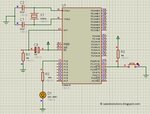
a small demo :)pfa)


one more external interrupt example

https://saeedsolutions.blogspot.in/2012/06/8051-at89c51-external-interrupt-int0.html


Best wishes,
 

Attachments

  • code.txt
    1 KB · Views: 95
  • 8051 int0 cct.JPG
    8051 int0 cct.JPG
    129.4 KB · Views: 128
  • Like
Reactions: m8052

    m8052

    Points: 2
    Helpful Answer Positive Rating
Now here is what I have. I think if you look at the whole lot, you can understand better what I am trying to achieve :)
My questions are below :)

Code:
#include<reg51.h>
#include<stdio.h>

#define datadefine P2
int i;
int j;
sbit lcd_rs=P0^5;
sbit lcd_rw=P0^6;
sbit lcd_en=P0^7;
sbit button=P1^0;

sbit CASE1=P0^1;
sbit CASE2=P0^2;
sbit CASE3=P0^3;
sbit CASE4=P0^4;

bit update_flag=0x10;
bit time_possibilities=0x11;
bit zv_flag=0x12;
bit zc_flag=0x12;
bit lead_flag=0x12;
bit lag_flag=0x14;

int p,q;
unsigned char high_count, high_count1, low_count, low_count1, count, time_count;

unsigned int time_difference,time;

void init_lcd();
void delay1(int i, int j);
void BusyCheck();

void lcdcmd (unsigned char cmd);
void lcddata (unsigned char datas);
void lcdstring (unsigned char *str);


void int0_ZVS(void) interrupt 0

{
if (lag_flag==1)

{

TMOD|=0x10;
TH1=0x00;
TL1;0x00;
TR1=1;
zv_flag=1;
}
if (zc_flag==1)

{

zc_flag=0;
TR1=0;
high_count=TH1;
low_count=TL1;
time_possibilities=1;
}
}

void int1_ZCS_ISR (void)interrupt 1

{

if (lead_flag)
{


TMOD=0x10;
TH1=0x00;
TL1=0X00;
TR1=1;
zc_flag=1;
}

if (zv_flag==1)

{

zv_flag=0;
TR1=0;
high_count=TH1;
low_count=TL1;
time_possibilities=1;
}

}

void timer()
{
TMOD=0x01;
TH0=0x00;
TL0=0x00;
}
void main()


{
init_lcd();
lcdstring("Welcome");
lcdcmd(0xc0);
lcdstring("POWER FACTOR 1");

delay1(i,j);

zv_flag=0;
zc_flag=0;
lead_flag=0;
lag_flag=0;
time_possibilities=0;
time_count=0;
count=1;

while (1)

{
                            if (button==1)

                        {

                    if (count==1)

                {

CASE1=1;
CASE2=0;
CASE3=0;
CASE4=0;

                } 

                    if (count==2)

                {

CASE1=1;
CASE2=1;
CASE3=0;
CASE4=0;

                } 

				
                    if (count==3)

                {

CASE1=1;
CASE2=1;
CASE3=1;
CASE4=0;

                } 	


                    if (count==4)

                {

CASE1=1;
CASE2=1;
CASE3=1;
CASE4=1;

                } 	   


                       		else

                {

CASE1=0;
CASE2=0;
CASE3=0;
CASE4=0;

                }	

                             if(time_possibilities==1)

                        {
high_count1=high_count;
low_count1=low_count;

time_difference=((((256*high_count1)+low_count1)*1.085));
time_difference=time;
                     if((time>9000)||((time>0)&&(time<600)))

               {
lcdcmd(0x80);
lcdstring("pf=1");
            if (button==1)
						

        {

lcdstring("I phase");


        }

            else 

{


lcdstring ("I phase");


}

lcdstring("Time diff=0");


}
			
                     if((time>600)&&(time<1000))

               {
lcdcmd(0x80);
lcdstring("pf=0.95");
            if (button==1)

        {

lcdstring("Current Leads");


        }

            else 

{


lcdstring ("Current Lags");


}
lcdcmd(0xc0);
lcdstring("Time diff=0-1");

              }

                     if((time>1000)&&(time<2000))

               {
lcdcmd(0x80);
lcdstring("pf=1");
            if (button==1)

        {

lcdstring("Current Leads");


        }

            else 

{


lcdstring ("Current Lags");


}
lcdcmd(0xc0);
lcdstring("Time diff=1-2");

              }

                      if((time>2000)&&(time<3000))

               {
lcdcmd(0x80);
lcdstring("pf=0.61");
            if (button==1)

        {

lcdstring("Current Leads");


        }

            else 

{


lcdstring ("Current Lags");


}
lcdcmd(0xc0);

lcdstring("Time diff=2-3");

              }

                    if((time>3000)&&(time<4000))

               {
lcdcmd(0x80);
lcdstring("pf=0.32");
            if (button==1)

        {

lcdstring("Current Leads");


        }

            else 

{


lcdstring ("Current Lags");


}
lcdcmd(0xc0);
lcdstring("Time diff=3-4");

              }

                      if((time>4000)&&(time<5000))

               {
lcdcmd(0x80);
lcdstring("pf=0.10");
            if (button==1)

        {

lcdstring("Current Leads");


        }

            else 

{


lcdstring ("Current Lags");


}
lcdcmd(0xc0);
lcdstring("Time diff=4-5");

              }			  
			
delay1();
time_count++;
if (time_count==6)


{

time_count=0;
count++;

}


}
				
				
                         }


}


}

//void delay1()

//{
//int p,q;
//for (p=0;p<500;p++);
//for (q=0; q<3000;q++);

//}

void lcdcmd(unsigned char cmd)

{
datadefine=cmd;
lcd_rs=0;
lcd_rw=0;
lcd_en=1;
lcd_en=0;
}

void lcddata(unsigned char datas)


{

datadefine=datas;
lcd_rs=1;
lcd_rw=0;
lcd_en=1;
lcd_en=0;
}

void lcdstring(unsigned char *str)

{
while(*str)

{
lcddata(*str);
str++;

}
}
void init_lcd()
{
lcdcmd(0x38);
lcdcmd(0x06);
lcdcmd(0x0c);
lcdcmd(0x02);
}

void delay1( int i,  int j) {


        for(i=0; i<1000; i++)
                for(j=0; j<100; j++)
                        i = i + 0;
}

Thanks for your reply. That was a very nice example of the interrupts.

Now from that example, interrupts are inside the void main. Is it ok to put it just before the void(main) or does it matter?

Just before the main, I have initiliased the timer 0 (this is seperate from timer1), is this how you do it? or you can use timer1 and it wont be mixed up?
Do i need different timers for voltage and current? Can I use the TH and TL registers for this?

Sorry but I am pretty new to this and still trying to figure out. If my questions are a bit stupid, I deeply apologise.

Is that your blog btw?

Thanks for your help :)

Edit: I am using keilvision 4 to compile it and wellar programming to program the AT89S52 :)
 
Last edited:

bit variables even though 8-bit sized are used to hold bit values like 1 and 0. You are assigning values like 0x12 etc to bit variables. What is the use of doing like that?
 
  • Like
Reactions: m8052

    m8052

    Points: 2
    Helpful Answer Positive Rating
bit variables even though 8-bit sized are used to hold bit values like 1 and 0. You are assigning values like 0x12 etc to bit variables. What is the use of doing like that?

This is exactly where i get confused with flags. I need to use flags so that the program can jump to interrupt task, how can i accomplish that? Thank you.
 

What do you mean by jumping to interrupt task? You want to jump to a code which starts a timer interrupt? Usually when interrupt occurs a flag is set so that a piece of code in while(1) loop can be executed if flag is set. Tell exactly what you are trying to do. If you are using a timer0 interrupt for 10 ms then a timer interrupt is caused every 10 ms and you have to clear the timerx interrupt flag and then set a flag and then you check if this flag is set in the while(1) loop and then execute some code and clear the flag.
 

Status
Not open for further replies.

Similar threads

Part and Inventory Search

Welcome to EDABoard.com

Sponsor

Back
Top