iceblu3710
Member level 3
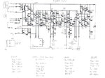
I have a copy of the repair schematics for my power supply and I spent the weekend tracing out components and verifying connections and values. The PCB is 95% the same as the schematic outside of an extra transistor to drive the output FET and a few diodes (You can see them drawn in on the cct)
**broken link removed** (Attachment #1)
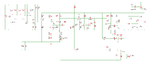
I then proceeded to input the circuit into SIMetrix the spice tool I use on Linux. That took a bit of time but I got it all inputted with the correct values and my simulations are somewhat correct. The main problem I am having is that the transistors are quite old. The 2SA495 datasheet I found said it was retired in 1977 so I have no accurate spice models for these transistors. Currently I am using the basic NPN/PNP models with Hf being the only value I supplied ( .model A495 PNP(Hf=67) )
**broken link removed** (Attachment #2)
Does anybody know how I can make my model more accurate? During simulation I can sweet the load resistance and the voltage will drop as the current goes up to keep a constant power output as expected but the voltage and current adjustment pots (RV3/4/5) do absolutely nothing.
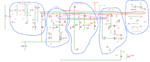
So without working models I decided to conceptualize the working of the circuit and I was able to break into into 5 main components.**broken link removed** (Attachment #3) Without working models I am not sure exactly how the voltage and current sections impose their will on the output rail. The control rail seems to be interesting as the output voltage(V3 or V4) is added to the control voltage (V5) to make sure the control rail is always above the (+) output on the front of the supply.
So before I can start to see whats wrong with this PSU I need to know some current resistor equivalents so I can simulate things properly. Anybody know replacements for these?
2SC2120
2SC2481
2SC372
2SA495
What looks like a Toshiba D718 FET marked (T D718 O) (This is the output transistor)
EDIT - Attachments don't seem to be working so I added external links as well.
**broken link removed** (Attachment #1)
I then proceeded to input the circuit into SIMetrix the spice tool I use on Linux. That took a bit of time but I got it all inputted with the correct values and my simulations are somewhat correct. The main problem I am having is that the transistors are quite old. The 2SA495 datasheet I found said it was retired in 1977 so I have no accurate spice models for these transistors. Currently I am using the basic NPN/PNP models with Hf being the only value I supplied ( .model A495 PNP(Hf=67) )
**broken link removed** (Attachment #2)
Does anybody know how I can make my model more accurate? During simulation I can sweet the load resistance and the voltage will drop as the current goes up to keep a constant power output as expected but the voltage and current adjustment pots (RV3/4/5) do absolutely nothing.
So without working models I decided to conceptualize the working of the circuit and I was able to break into into 5 main components.**broken link removed** (Attachment #3) Without working models I am not sure exactly how the voltage and current sections impose their will on the output rail. The control rail seems to be interesting as the output voltage(V3 or V4) is added to the control voltage (V5) to make sure the control rail is always above the (+) output on the front of the supply.
So before I can start to see whats wrong with this PSU I need to know some current resistor equivalents so I can simulate things properly. Anybody know replacements for these?
2SC2120
2SC2481
2SC372
2SA495
What looks like a Toshiba D718 FET marked (T D718 O) (This is the output transistor)
EDIT - Attachments don't seem to be working so I added external links as well.
Attachments
Last edited: