Continue to Site

Welcome to EDAboard.com

Welcome to our site! EDAboard.com is an international Electronics Discussion Forum focused on EDA software, circuits, schematics, books, theory, papers, asic, pld, 8051, DSP, Network, RF, Analog Design, PCB, Service Manuals... and a whole lot more! To participate you need to register. Registration is free. Click here to register now.

Firing of High power thyristors

Status
Not open for further replies.

ravi2024

Newbie level 6
Joined
Jul 7, 2013
Messages
11
Helped
0
Reputation
0
Reaction score
0
Trophy points
1
Activity points
94
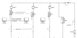
I am designing a capacitive discharge circuit to heat an alloy. The ckt is attached. I have to build this circuit in practical also for a project. I need to fire the thyristors in every branch once to discharge the capacitor. After the discharge time of milliseconds the other branch shoud be fired with time gap of milliseconds only after the firing of the first thyristor... and the same for the third one. How do I achieve this firing and from where can i buy the firing circuit.


thanx
 

Attachments

  • circuit.png
    circuit.png
    43.4 KB · Views: 110

If are you ready to work with soldering iron you can make the firing circuit by your hands.

Way #1:
Symmetrical multivibrator
https://rayshobby.net/blog/wp-content/uploads/2011/11/multivibrator2.png
but you should do three sections.
+ 555timers to form short impulses.

Way #2:
Microcontroller circuit with easy program.

If you have interest I can give more detailed help.
 
Thnx for the reply! Yeah I am very interested to do this... any help is appreciated. I have decided to use Thyristors instead of GTOs. So to fire these within milliseconds after each other which of the two methods is more suitable?
 

Way #2 is better.
Do you familar with some microcontrollers?

You can make your circuit on the: https://electronics.stackexchange.com/questions/55236/how-to-make-traces-on-an-universal-pcb connecting details with wires (see only photo!).
If you are not familar with microcontrollers, I can help to make firmware for PIC microcontroller, for example PIC18F1320 or better PIC12F629. I have this now and can try firmware.
But in any case you will need programmer to program your PIC. You will have to find this in your area. Example - PICKit 2 or 3. Or other that can work with PIC.

Do you have the thyristors? You can chose this by max current and voltage. And you will need to make three transformers on the ferrite rings. And three transistors to drive this transformers. And some diodes, resistors and capasitors.

If are you ready for this challenge - let's go :)
 
HI! Sorry for the late reply. I was out of town for few days. I am ready for it now. The only problem is the micro-controller part. Lets see if we can do something about that. There are 3 numbers of capacitors being discharged using 3 thyristors so i need to trigger 3 thyrsitors for one shot only. The di/dt rise of the anode current will be very high of the order of 250A/us so the gate triggering pulse should be of about 2.5 Amps for about 5ms. The gate cathode voltage should be arnd 20 V. These high output ratings are also a problem i guess.
 

You didn't tell about the thyristor type, so I can't check if it actually needs 2.5A trigger current. But in any case, it won't need it for 5 ms. A few 10 µs will be sufficient.

I would primarly think of trigger transformers to supply the gate voltage.
 
The thyristor datasheet is this one:
**broken link removed**
the second thyristor should be fired about 3-5 millisecs after the first one and the third thyristor about 3-5 millisecond after the secons one. Its a one shot discharge so firing also needed of a single pulse.
 

O.K. the datasheet suggests 20V/10 ohm trigger circuit for rated dI/dt, the pulse duration can be considerably shorter than 5 ms I think, trigger delay is e.g. specified with 1.9 us. The pulse duration hasn't to do with the 5 ms sequence time step, I think, it can be generated seperately.
 

Thanx for the reply. SO What components should i sue and how should i proceed towards it?

- - - Updated - - -

I am also ready to buy some components from the market to build the driving circuit.
 

What are Current1, Current2 and Current 3? Is it just current sensors?
I can't understand how this thyristors drived. In manual: "anode to cathode" on your circuit cathode to anode.
If thyristors have common point you can fire thyristors with bipolar transistors. Transistors can be drived by Smitt trigers with RC-circuits for time delays.
 

Yes, Current 1,2 and 3 are current measuring devices during simulation. In my circuit also voltage is applied anode to cathode by Capacitors charged up to 500V. Thyristors dont have common point. Capacitors will be discharged one by one after each other.
 

Status
Not open for further replies.

Similar threads

Part and Inventory Search

Welcome to EDABoard.com

Sponsor

Back
Top