jeff0283
Junior Member level 2
Hi, I am doing the em cosimulation of my board,which is the output matching of PA, and I want to see the difference between infinite ground plane and finite ground plane.
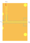
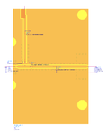
Here are my layout and substrate setup and schematic with finite ground plane.
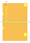

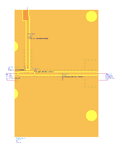
I set cond1(pink) as the top metal,and cond2(yellow) as the bottom metal. Because I use CPWG, the holes are placed to connect the cond1 with cond2.
Is it right for finite ground plane?
For the port setup, I've tried two ways
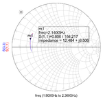
1. I set all the pins as global ports:

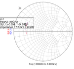
2. I set (Pin1,10),(Pin2,11),(Pin3,13) as three differential ports,and other pins remain global ports.

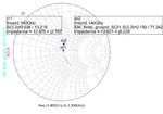
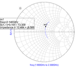
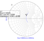
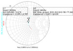
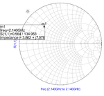
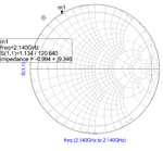
But the results are different, I don't know why....
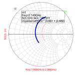 (red is for global ports and blue is for differential ports)
Could anyone give me some advice??
Thanks~~
Here are my layout and substrate setup and schematic with finite ground plane.


I set cond1(pink) as the top metal,and cond2(yellow) as the bottom metal. Because I use CPWG, the holes are placed to connect the cond1 with cond2.
Is it right for finite ground plane?
For the port setup, I've tried two ways
1. I set all the pins as global ports:

2. I set (Pin1,10),(Pin2,11),(Pin3,13) as three differential ports,and other pins remain global ports.

But the results are different, I don't know why....
 (red is for global ports and blue is for differential ports)
Could anyone give me some advice??
Thanks~~
