Continue to Site
Follow along with the video below to see how to install our site as a web app on your home screen.
Note: This feature may not be available in some browsers.
")
Exercises, exercises and after... more exercises.Hello
I'm reading the circuit analysis.i know writing of differential equations but not very familiar to solve them with mathematical ways.
could you tell me the best reference to know them?what you suggest?
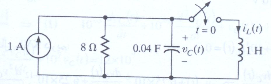
in the above circuit i want to know how can find the capacitor current at 0+
You could use a circuit simulator and let your computer do the maths for you.I'm reading the circuit analysis.i know writing of differential equations but not very familiar to solve them with mathematical ways.
Capacitor current at t=0+ is Infinite
Note that an ideal inductor has zero resistance. At t=0+ there is NO magnetic field present.
Naturally this situation only lasts for delta --> 0 time period.

HOWEVER, we are NOT talking about steady-state analysis.
We are ONLY talking about the infinitisemal time immediately after closure of the "perfect" switch.
Thats what t=0+ means.
The capacitor current is never infinite.
An ideal inductor has zero DC resistance, but it has inductance. When a voltage is applied, the current increases from zero at a rate that depends on the inductance and the voltage.
Even with a perfect inductor, it would take an infinite amount of time for the current to rise to infinity.
rohitkhanna,
The Laplace transform gives the total response. As you can see, there is no high current spike, just a nondecaying sinusoidal response. In order to obtain a high current spike, you would have to have a perfect cap shorted out by a superconductor wire.
Ratch
Lets take the converse case of a CAPACITOR - an ideal one with zero initial charge, no resistance, no inductance - being instantantly connected to an ideal voltage source source (ideal here means - zero output resistance, infinite current capability).
What do you think will be the current at the instant of connection ? I claim it will be infinite and the cap will charge up to the voltage of the source instantly. Why would it not ? What is there to stop the current going to infinity ?
Similarly, when you connect an ideal Cap to an ideal Inductor 'suddenly', what exists at THAT INSTANT OF TIME to stop the flow of current ?
Really ? Laplace does that ? I always thought it worked on linear integrals & differentials, not on discontinous functions.
So whats the Laplace transform of the Dirac delta then ? I need to know this for a project I'm working on.....
Secondly - regarding the perfect cap etc etc comment. Is that not what the question was all about ? A perfect cap of 0.4F and a perfect Inductor ( i.e. ZERO resistance - never mind the superconducting point, & zero capacitance) of 1H etc ?? .