userx2
Full Member level 3
Hello,
I must admit, I have always had problems with Fet's not lasting in many applications I have used them as well as seen used by others.
This ranges from welding machines, light dimmers, motor controllers etc.
I never found the real reasons why this happens.
One other designer told me once that he moved away changed his designs to use IGBTs instead since they do not seem to have this issue.
Now I have a circuit that a former colleague of mine designed into one of our products. This one controls a 240V mains operated solenoid valve.
Now, about a year or so down the line, failures have started to emerge where the Fet's are burned out and there is again no easy explanation.
I am now considering changing the circuit to use a triac instead. They do last but have more power dissipation and heat generation
Perhaps someone here has better experience and can share their thoughts what may be happening here?
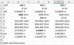
The solenoid is 230V 6W
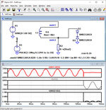
The circuit looks as attached. There are 2 Fets and 2 opto isolators to drive the gate voltage.
Either one or both Fets go faulty and will be cracked open or just black bits remaining.
I personally cannot find anything underrated or wrong with the circuit. The mains has MOVs on it as well at the input of the PCB.
Q2 and or Q6 seem to blow up. So far, it is 5 out of 200 delivered units and it happens after a month or longer. Hard to say what customers do with the unit.
The solenoid itself is usually found open circuit as well (yes open, not shorted).

I must admit, I have always had problems with Fet's not lasting in many applications I have used them as well as seen used by others.
This ranges from welding machines, light dimmers, motor controllers etc.
I never found the real reasons why this happens.
One other designer told me once that he moved away changed his designs to use IGBTs instead since they do not seem to have this issue.
Now I have a circuit that a former colleague of mine designed into one of our products. This one controls a 240V mains operated solenoid valve.
Now, about a year or so down the line, failures have started to emerge where the Fet's are burned out and there is again no easy explanation.
I am now considering changing the circuit to use a triac instead. They do last but have more power dissipation and heat generation
Perhaps someone here has better experience and can share their thoughts what may be happening here?
The solenoid is 230V 6W
The circuit looks as attached. There are 2 Fets and 2 opto isolators to drive the gate voltage.
Either one or both Fets go faulty and will be cracked open or just black bits remaining.
I personally cannot find anything underrated or wrong with the circuit. The mains has MOVs on it as well at the input of the PCB.
Q2 and or Q6 seem to blow up. So far, it is 5 out of 200 delivered units and it happens after a month or longer. Hard to say what customers do with the unit.
The solenoid itself is usually found open circuit as well (yes open, not shorted).
Last edited by a moderator: