hkBattousai
Advanced Member level 4
**broken link removed**
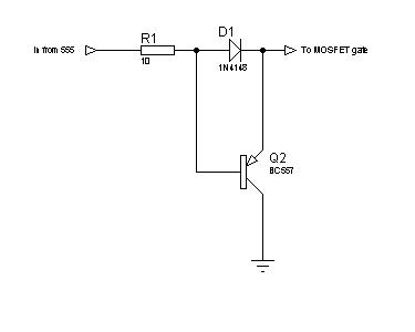
I'm designing a switch mode power supply which can be described by the block diagram above. The pulse generator circuit consists of a 555. Output of 555 is directly connected to the gate of the MOSFET (6N60). A 100Ω resistor is connected to the secondary windings of the ferrite core as load. I tried different supply voltages from 5V to 12V, higher the voltage better the waveform and the MOSFET heats up more.
When I connect a commutating diode to the primary windings, I observe a better waveform at the both transformer windings (better: sharper edges, more swing).
I'm not familiar with ferrite cores, so I am having troubles at that part of the circuit. I need a ferrite core driving circuit which is better than the one above.
Can you guys please suggest me a better way of driving this ferrite core transformer?
EDIT: Opps, I realized that I put the "Filter & Regulator" block twice, it should have appeared only once.