Continue to Site

Welcome to EDAboard.com

Welcome to our site! EDAboard.com is an international Electronics Discussion Forum focused on EDA software, circuits, schematics, books, theory, papers, asic, pld, 8051, DSP, Network, RF, Analog Design, PCB, Service Manuals... and a whole lot more! To participate you need to register. Registration is free. Click here to register now.

Ferrite core driving circuit?

Status
Not open for further replies.

hkBattousai

Advanced Member level 4
Joined
Jun 16, 2007
Messages
118
Helped
5
Reputation
10
Reaction score
1
Trophy points
1,298
Location
Turkey
Activity points
2,182
**broken link removed**

I'm designing a switch mode power supply which can be described by the block diagram above. The pulse generator circuit consists of a 555. Output of 555 is directly connected to the gate of the MOSFET (6N60). A 100Ω resistor is connected to the secondary windings of the ferrite core as load. I tried different supply voltages from 5V to 12V, higher the voltage better the waveform and the MOSFET heats up more.

When I connect a commutating diode to the primary windings, I observe a better waveform at the both transformer windings (better: sharper edges, more swing).

I'm not familiar with ferrite cores, so I am having troubles at that part of the circuit. I need a ferrite core driving circuit which is better than the one above.

Can you guys please suggest me a better way of driving this ferrite core transformer?

EDIT: Opps, I realized that I put the "Filter & Regulator" block twice, it should have appeared only once.
 

why the ferrite py winding is grounded ?
why not connected to the +ve supply ?

(your drawing is good and explanatory . did you use orcad shematic to generate this or anything else ?)

Added after 3 minutes:

any reason to use p-channel mosfet ?
 

    hkBattousai

    Points: 2
    Helpful Answer Positive Rating
srizbf said:
why the ferrite py winding is grounded ?
why not connected to the +ve supply ?
I tried connecting the MOSFET to the lower side too, but it didn't make very much change.


srizbf said:
(your drawing is good and explanatory . did you use orcad shematic to generate this or anything else ?)
I used "Microsoft Visio" for entire drawing.


srizbf said:
any reason to use p-channel mosfet ?
That's n-MOSFET in my circuit, I used the wrong symbol in the schematics.
 

if it is an nmosfet , then you should connect the ferrite py winding to +ve supply.

as 555 has 0 to +ve voltage only .

mosfet :source -->ground.
drain -->py wdg terminal 1
gate--> from 555 o/p

py wdg terminal2 -->+ve supply.
have a diode across the primary as shown
 

    hkBattousai

    Points: 2
    Helpful Answer Positive Rating
srizbf said:
if it is an nmosfet , then you should connect the ferrite py winding to +ve supply.

as 555 has 0 to +ve voltage only .

mosfet :source -->ground.
drain -->py wdg terminal 1
gate--> from 555 o/p

py wdg terminal2 -->+ve supply.
have a diode across the primary as shown
Ok, I will try that configuration now...

My current circuit is like this:
**broken link removed**

All I'm trying to see is that, a 5Vp-p pulse in primary windings is directly transferred to the secondary windings (of course there will be some loss).

After a little research I learned that a ferrite core can transfer signals with frequency up to MHz levels. Output frequency of 555 is about 50kHz. At least the first 20 harmonics of these clock pulses will be transferred successfully, wouldn't they? If so, I expect to see the very same clock pulses on the primary side.

Added after 1 hours 14 minutes:

srizbf said:
if it is an nmosfet , then you should connect the ferrite py winding to +ve supply.

as 555 has 0 to +ve voltage only .

mosfet :source -->ground.
drain -->py wdg terminal 1
gate--> from 555 o/p

py wdg terminal2 -->+ve supply.
have a diode across the primary as shown

I tried your suggestion:

Vcc = 5V
Average current drain = 175mA
555 frequency = 50kHz

Circuit:
**broken link removed**

Gate voltage:
**broken link removed**
2 V/square

Source voltage ("source" pin of 6N60), with commutating diode:
**broken link removed**
2 V/square

Source voltage ("source" pin of 6N60), without commutating diode:
**broken link removed**
2 V/square

Primary winding current (drain current):
**broken link removed**
10 mV/square on 0.1 Ohm resistance ==> 100 mA/square

Primary winding voltage, with commutating diode:
**broken link removed**
1 V/square

Primary winding voltage, without commutating diode:
**broken link removed**
1 V/square

Secondary winding voltage, with commutating diode:
**broken link removed**
1 V/square

Secondary winding voltage, without commutating diode:
**broken link removed**
1 V/square


When you compare primary and secondary winding voltages, you see that the waveform in primary windings is successfully transferred to the secondary windings.
The problem here is driving the primary windings. As you see from primary windings voltage waveform, I cannot drive the primary windings with a full 5V swing voltage. I want to achieve this. Can you please suggest me how to do it?

And a critical issue: my final purpose on this project is to drive the primary windings with 310V and obtain 5V on the secondary windings. Please refer to this thread for more information. That's why I placed the transistor on the GND side. This current circuit is only for testing and learning the principles of the ferrite core transformer.
 

if full 5v is to be applied in py wndg , then connecting py to 'source' terminal is not recommended.
i hope that you have not interchanged the pins S and D of MOSFET.

connecting to drain terminal alone will have full 5v across py.

your testing waveforms does not give any info on 'dc level '(ref line for dc)
somewhat difficult to comprehend.

when you test with a toroid see that you are not loading it heavily .
 

Hi,
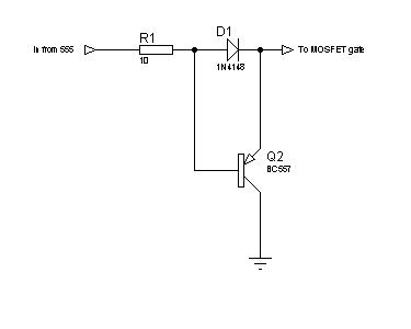
If it is an N-channel MOSFET, connect the source to ground, and the transformer between drain to +ve supply. Connect a snubber across the primary. Instead of 5v, use 12v, as 12v turns the MOSFET on fully.
In between the 555 and MOSFET, connect a driver. There are many: totem-pole, diode-transistor, IC, etc.

You can try this:
2_1279208870.jpg


Hope this helps.
Tahmid.

Added after 2 minutes:

If you're looking to anything more efficient and dedicated to the task, take a look at:
**broken link removed**
 

    hkBattousai

    Points: 2
    Helpful Answer Positive Rating
Status
Not open for further replies.

Similar threads

Part and Inventory Search

Welcome to EDABoard.com

Sponsor

Back
Top