alexan_e
Administrator
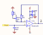
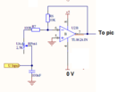
Basically you want to make https://en.wikipedia.org/wiki/Operational_amplifier#Non-inverting_amplifier
using Vcc and GND as supply , is that right?
using Vcc and GND as supply , is that right?
Follow along with the video below to see how to install our site as a web app on your home screen.
Note: This feature may not be available in some browsers.