Continue to Site

Welcome to EDAboard.com

Welcome to our site! EDAboard.com is an international Electronics Discussion Forum focused on EDA software, circuits, schematics, books, theory, papers, asic, pld, 8051, DSP, Network, RF, Analog Design, PCB, Service Manuals... and a whole lot more! To participate you need to register. Registration is free. Click here to register now.

Faulty acer 5315 LA-3551P Motherboard

Status
Not open for further replies.

refurb.tech

Newbie level 4
Joined
Nov 11, 2012
Messages
7
Helped
0
Reputation
0
Reaction score
0
Trophy points
1,281
Activity points
1,334
Hi there

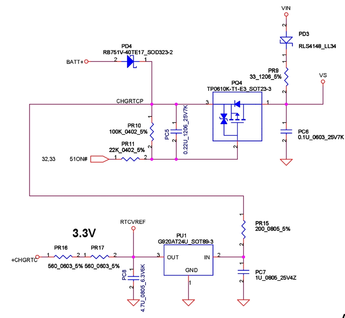
i have a faulty acer 5315 / compal la-3551p motherboard with no charge light, no power up and the fault that i know of is a burnt out RB751V-40TE17 which i believe from a bit of research is a 40V 30MA SOD-323 Schottky barrier diode, i have removed the broken diode and was wandering if bridging the pad's will get the board working temporarily just to know if it is the only problem or would it damage further ?

i have been trying for a number of years to learn board level repair on my own, but get so frustrated after a few weeks of trying to understand and failing, that i leave it for a few months and then try again at which point i fail again and so for bout 6 years lol i have gotten mostly nowhere. was also hoping that some of you would be able to help me get a better understanding of where i am going wrong with my learning.

DCIN.DECTOR.jpg

i have the schematic also, so if anyone needs it please let me know and i will mail it.

thanx
 
Last edited:

hi.bridge will make the fault worse.try asking why it burnt,i.e find the source.good luck.
 

looking at the image, would i be right in assuming that the current flows from pq4 to pd4 then to bat+ or is it the other way around ? i have checked continuity between pd4 / pq4 then pq4 / pr9 then pr9 / pd3 and there is no break however when i test pr9 using my testers set to 200 ohms the value i get starts at 100 and then works its way down to about 80 to 85. pr9 i believe is a 0.330 ohms resister so am i getting the right value or am i missing something / doing something wrong ?
 

looking at the image, would i be right in assuming that the current flows from pq4 to pd4 then to bat+ or is it the other way around ?
from bat+ to pd4 then to pq4 and pr15 to pu1 and VS or from VIN to pd3 then pr9 to pq4 and VS then to pr15
pr9 i believe is a 0.330 ohms resister so am i getting the right value or am i missing something / doing something wrong ?
pr9 is a 33 ohms. If the value begins at 100, PR9 is lightly damaged when burned pd4.
 
thats brilliant ! thanks, its funny you would say pr9 lightly damaged as well, the one thing i didnt say was that once i had tested pr9 i had a closer look and it indeed did have a small burn mark at the bottom of it and also the value was no longer legible on the surface, whereas the resisters of that type were all readable.

do you think these two problems together would result in no charge and no boot ?

many thanks for your help
 

do you think these two problems together would result in no charge and no boot ?
Maybe, but your drawing is related to RTC (Real Time Clock) charging (+CHRGRTC signal) and referencing (RTCVREF).

if bridging the pad's will get the board working temporarily
Have you in mind short the pd4 pads?
 

yes, i have already shorted the pads before i found the faulty resister and still no charge or no boot, maybe i should replace the two faulty parts and see if it will charge and maybe power on, the schematic puts this as part of the ac and battery precharge detector, and maybe i'm not reading it right but the circuit also links to the power button i will attach an image below, let me know what you think.


Status
Not open for further replies.

Part and Inventory Search

Welcome to EDABoard.com

Sponsor

Back
Top