refurb.tech
Newbie level 4

- Joined
- Nov 11, 2012
- Messages
- 7
- Helped
- 0
- Reputation
- 0
- Reaction score
- 0
- Trophy points
- 1,281
- Activity points
- 1,334
Hi there
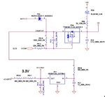
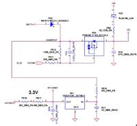
i have a faulty acer 5315 / compal la-3551p motherboard with no charge light, no power up and the fault that i know of is a burnt out RB751V-40TE17 which i believe from a bit of research is a 40V 30MA SOD-323 Schottky barrier diode, i have removed the broken diode and was wandering if bridging the pad's will get the board working temporarily just to know if it is the only problem or would it damage further ?
i have been trying for a number of years to learn board level repair on my own, but get so frustrated after a few weeks of trying to understand and failing, that i leave it for a few months and then try again at which point i fail again and so for bout 6 years lol i have gotten mostly nowhere. was also hoping that some of you would be able to help me get a better understanding of where i am going wrong with my learning.

i have the schematic also, so if anyone needs it please let me know and i will mail it.
thanx
i have a faulty acer 5315 / compal la-3551p motherboard with no charge light, no power up and the fault that i know of is a burnt out RB751V-40TE17 which i believe from a bit of research is a 40V 30MA SOD-323 Schottky barrier diode, i have removed the broken diode and was wandering if bridging the pad's will get the board working temporarily just to know if it is the only problem or would it damage further ?
i have been trying for a number of years to learn board level repair on my own, but get so frustrated after a few weeks of trying to understand and failing, that i leave it for a few months and then try again at which point i fail again and so for bout 6 years lol i have gotten mostly nowhere. was also hoping that some of you would be able to help me get a better understanding of where i am going wrong with my learning.

i have the schematic also, so if anyone needs it please let me know and i will mail it.
thanx
Last edited:


