Continue to Site

Welcome to EDAboard.com

Welcome to our site! EDAboard.com is an international Electronics Discussion Forum focused on EDA software, circuits, schematics, books, theory, papers, asic, pld, 8051, DSP, Network, RF, Analog Design, PCB, Service Manuals... and a whole lot more! To participate you need to register. Registration is free. Click here to register now.

facing problem with moc3021

Status
Not open for further replies.

majinbuu

Newbie level 5
Joined
Jan 28, 2012
Messages
8
Helped
0
Reputation
0
Reaction score
0
Trophy points
1,281
Activity points
1,341
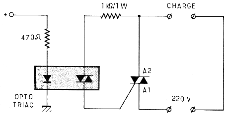
i m trying to interface optocoupler moc3021 with controller , the problem that i m facing is that , when i give 5v to its anode and 0 to its cathode , the bulb as my load should glow completely but it is not glowing at all , can someone please help on this , please someone help me out.....
 

I hope you have spare MOC3021 - connecting anode to 5V and cathode to GND without resistor for sure will burn up the device.
 
How did you connect the lamp and the MOC3021?
Did you connect the anode directly to +5V? No resistors?
Did you drive the lamp with the MOC3021? Did you use another triac? If so, did you limit the current from the MOC3021 to the triac?
 
correct wiring of a moc30xx and his charge
beware the a2 pin MUST be connected to the moc, and not the A1...
83_1327772502.png
 
well guyz thanks for your advices , i used a resister of 1k , i think that should make the led safe , but i think it might not have glown enough to start the diac , i think that might have been the problem .

---------- Post added at 07:22 ---------- Previous post was at 07:20 ----------

How did you connect the lamp and the MOC3021?
Did you connect the anode directly to +5V? No resistors?
Did you drive the lamp with the MOC3021? Did you use another triac? If so, did you limit the current from the MOC3021 to the triac?
well used the ckt that was given in the datasheet , the sensitive one , i think that would have limited the current .

---------- Post added at 07:25 ---------- Previous post was at 07:22 ----------

correct wiring of a moc30xx and his charge
beware the a2 pin MUST be connected to the moc, and not the A1...
83_1327772502.png

thankyou for the reply , but i have one small doubt why do attach 470ohm resister and not any other , i mean why is 470 a standard value for driving the led , like when we use normal ckts in avr also we use a 4.7k resister to to pullup the ckt , i hope you got my doubt .
 

in the moc3021, the led must have 15mA and 1.2V to "light on" ...
so you choose your resistor depending on the voltage you have to switch it
if you have 5V, (5v-1.2v)/0.015 = 250Ω
for 12v : 720Ω
this value is not very critical, but 1KΩ seems quite a lot to light up a led enought. specially for a 5v command
470Ω is a good medium value that should work for many low voltages.
 

hey guyz though the problem with glowing the bulb is done i m not able to control its intensity using PWM . i used a pulse of 20ms and made it on for 5ms and off for 15ms now what i though was that this should make the bulb intensity to go low but it is flickring from low to high , i mean that its intensity is going from 0 to maximum and then to zero and this continues , any sugestions what mistake i m making.
 

You need to detect zero crossing of mains voltage and then set trigger pulse after a delay.This delay will set brightness. Your timing is not right. You should consider half cycle, which will be 10mS maximum. As you are not synchronizing. You are superimposing two close frequencies and observing beat frequency (Mains and 50Hz from your source).

https://www.edaboard.com/threads/181497/

**broken link removed**

RMS Voltage Control Circuit with MOC3021 and BT136 - Telecommunication and Electronics Projects
 
Last edited:

Let me explain the problem assuming that you require 20% brightness.

When you set PWM duty cycle (the traditional DC-DC controlling PWM) at 20%, the output is high for the first 2ms and low for 8ms. But as soon as the output goes high, the MOC3021 fires the triac, which gets latched (on) until the next zero crossing.
Take any duty cycle and you'll see that the lamp will always light upto full brightness.

What you have to do is, if you need 20% brightness:
Half period is 10ms. So, your output needs to be on for 20% first half, then 20% second half. So, that means 80% off, this 80% is "cut" through phase control. Wait for 80% of the half-time, ie, 8ms and THEN send a high pulse to the MOC for about 100us and then turn the pulse low. Repeat this for the second half as well, and THEN you will get 20% brightness.

Take a look at this:
Phase fired controllers - Wikipedia, the free encyclopedia

I've also explained this problem before here: https://www.edaboard.com/threads/215330/#post921549
https://www.edaboard.com/threads/215330/

Hope this helps.
Tahmid.

---------- Post added at 01:24 ---------- Previous post was at 01:22 ----------

Here's how it needs to be controlled:
220px-Regulated_rectifier.gif

Phase fired controllers - Wikipedia, the free encyclopedia
 
hey tahmid, i got 108.5vac for my load if i assign 5ms delay before firing triac.

is it mean that i turn it on 50% on the first half, and 50% the other half? my main is 50Hz 220V.

because the formula on internet says for 90degree of delay it will have 155Vrms
 

Im also having problems with moc3021. Good thing I found this forum. By the way , Im John Bohan . Nice to meet you all .

John Bohan

**broken link removed**
 

hey tahmid, i got 108.5vac for my load if i assign 5ms delay before firing triac.

is it mean that i turn it on 50% on the first half, and 50% the other half? my main is 50Hz 220V.

because the formula on internet says for 90degree of delay it will have 155Vrms

Hi,

What you have is 5ms off, then 5ms on in one 10ms half-cycle. That's 50% duty cycle - 50% first half and 50% second half. You'll get about 110VAC for this and you get 108.5VAC which is close enough.

What you found on the internet means that there's a delay (off before firing) for 5ms and then the triac is on for 15ms, the output voltage will be 155V. That's 75% duty cycle and is equivalent to having 2.5ms delay (off-time) and 7.5ms triac on, each 10ms half cycle.

Hope this helps.
Tahmid.
 
in my data collection for particular delays:
3ms=188.84
4ms=154.08
5ms=108.66

for 5ms it is 50% duty cycle. is it mean for 4ms is 60% and 3ms is 70%?

because if it is linear, my data collection is terrible.

i had found this graph , but it is delay vs power.

by let the 3ms is 85%, 4ms is 70%, then my collected data seems correct. sounds not scientific but i just dont know. what would you say about these?

is there any refference about duty cycle for phase firing angle? i need it for my final paper.
 

Attachments

  • 86_1175489946.gif
    86_1175489946.gif
    17.8 KB · Views: 90

It isn't linear - the change is sinusoidal. The graph you showed can also be used for voltage vs angle/time assuming current is constant.

For 3ms, V/Vmax is approximately 0.85, which means that Vout = 220V * 0.85 = 187V - close to what you get.
For 4ms, V/Vmax is approximately 0.7, which means that Vout = 220V * 0.7 = 154V - close to what you get.
For 5ms, V/Vmax is 0.5, which means that Vout = 220 * 0.5 = 110V - close to what you get.

So, your data collection seems good.

Hope this helps.
Tahmid.
 
Last edited:
so do you have any reference regrading to that result? maybe literature, graph, or the specific name of theory/method? i need it to be attached to my paper. you know, i cant just put forum as my reference in my scientific paper.

even the graph that i got is not mentioning any source. i got it in other edaboard post
 
Last edited:

Use the information from this: http://educypedia.karadimov.info/library/an1003.pdf

Hope this helps.
Tahmid.

i think mine refer to Figure AN1003.6 right? cmiiw

why the less conducting angle in previous graph = more voltage? but the less conduction angle in pdf means lower voltage. ( i assume that in pdf, conduction angle is 180-delay angle)


which one should i refer by the way, rms or avg?

how can i derive the graph of angle to get correct value for 220 main?
 
Last edited:

i interfaces my load as in picture. the main is rms right? but why i got rectified value instead of rms? i am wonder. because using pdf that u gave, 90 degree means 1/2 max voltage for average voltage, not rms. any help?
 

Attachments

  • moc3021.png
    moc3021.png
    12.9 KB · Views: 160

Status
Not open for further replies.

Part and Inventory Search

Welcome to EDABoard.com

Sponsor

Back
Top