Continue to Site

Welcome to EDAboard.com

Welcome to our site! EDAboard.com is an international Electronics Discussion Forum focused on EDA software, circuits, schematics, books, theory, papers, asic, pld, 8051, DSP, Network, RF, Analog Design, PCB, Service Manuals... and a whole lot more! To participate you need to register. Registration is free. Click here to register now.

FA5331P Buck boost PFC can't run at 100Vdc input

Status
Not open for further replies.

CafeNovember

Newbie
Joined
Feb 23, 2021
Messages
5
Helped
0
Reputation
0
Reaction score
0
Trophy points
1
Activity points
55
Hello dear forum
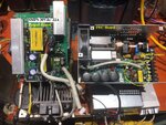
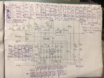
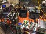
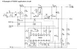
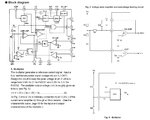
I am having 1 active PFC circuit as photo. Now I want it to work in the 95Vdc -> 130Vdc voltage range.
According to its original design it can work from 85 * 1.4142 = 120Vdc to 373Vdc.
Can anybody tell me how I need to make modifications to make it work and stable with such low input voltage.

Thank you and very interested
CafeNovember
 

Attachments

  • FA5331P.jpg
    FA5331P.jpg
    206 KB · Views: 88
  • FA5331P 2.pdf
    155.8 KB · Views: 54
  • FA5331- block.jpg
    FA5331- block.jpg
    211 KB · Views: 85
Last edited:

Did you check that the circuit doesn't work with 95 Vdc or is it just a guess?

A PFC boost converter works with continously varying input voltage, starting at 5 or 10 V. It's not designed to be supplied by DC input, but may work though.
 
Did you check that the circuit doesn't work with 95 Vdc or is it just a guess?

A PFC boost converter works with continously varying input voltage, starting at 5 or 10 V. It's not designed to be supplied by DC input, but may work though.

Thanks Mr. FvM
I have attached a picture of the power supply I am modifying.
I tried the voltage on 100Vdc then the output voltage is only 11Vdc, if it works properly then the output voltage should be 30Vdc.
I suspect that the voltage divider sent to pin 3 is below the 0.65V threshold causing the FA5331 to realize the input voltage is below the design threshold of the power supply (85-264Vac). Then the IC will control so that the power supply is not overloaded?
** PFC circuit uses 2 IC M51957B (Voltage detecting, System resetting). The power supply has Remote on / off control mode and input power loss warning.
Can you and someone help me fix this problem?
 

Attachments

  • smps.jpg
    smps.jpg
    403.4 KB · Views: 86
Last edited:

It's possible that the VDET pin needs to see more voltage for the thing to operate normally. But there's numerous other potential causes, impossible to say without having a schematic of the actual power supply (it's probably not identical to the application circuit in the FA5331 datasheet).

Can you provide some example waveforms/measurements?
 
Dear Mr mtwieg
I have measured voltage values on IC FA5531 at voltage values in operating range and below threshold. Including the situation I changed the resistor value of the bridge for the voltage divider for pin 3- VDET. The final measurement in the table, when R7-8 was changed, VDET = 0.76V> 0.65V but Vo = 96.3V showed that the Boost circuit was not running. I have suspected pin 12 (On / OFF) is overridden by the connection to IC M51957B. I attached datasheet M51957B, then I will go and re-draw the 12 pin circuit connected to it so you can help me find the problem.

Best Regards.
 

Attachments

  • Measure SMPS 1.jpg
    Measure SMPS 1.jpg
    291.5 KB · Views: 80
  • Measure SMPS 2.jpg
    Measure SMPS 2.jpg
    420.8 KB · Views: 65
  • m51957b.pdf
    219.9 KB · Views: 77
Last edited:

I adjusted M51957B to Vpin2 = 1.9V ( 1.28V before). FA5331 modify R7-8 = 430K. R6 = 3K. Then the circuit worked at Vin = 100Vdc. Vout = 366V but appears a little noise ~ 1.3V.
I started to try loading 3A-12A and 21A to see what happens.

The PFC circuit in this context is a PFC boost circuit for a switching power supply circuit (SMPS) 24V / 21A output Bucket behind. They are designed by manufacturers to work together.
Can any one tell me what will happen if I lower the Vout voltage of the PFC circuit lower? And if so, how low is SMPS circuit still working properly?

In this case I reduce Vin three times, For 1 bridge to divide the voltage for the parts such as voltage feedback, overvoltage protection feedback ... should I reduce the high side resistance (R7-8 440kOhm) or Will increasing low side resistance (R6 2k7) be better?

Someone passing by can help me with some clarification!

Thanks & Brgds
 

Is your goal to just convert 100VDC to 24VDC? If so, what's the point of having a boost stage at all? Why not just connect 100VDC directly to the step down converter?
 

Step down converter cannot work below 200Vdc. It is related to the ratio of the output step down pulse transformer.
Do you think when we reduce the input voltage of the step down converter to 240Vdc it will degrade in performance?
 

Step down converter cannot work below 200Vdc. It is related to the ratio of the output step down pulse transformer.
Understood. Even so, winding a new transformer might be simpler than modifying the boost converter.
Do you think when we reduce the input voltage of the step down converter to 240Vdc it will degrade in performance?
Impossible to say without details of the design.
 

Status
Not open for further replies.

Similar threads

Part and Inventory Search

Welcome to EDABoard.com

Sponsor

Back
Top