Continue to Site

Welcome to EDAboard.com

Welcome to our site! EDAboard.com is an international Electronics Discussion Forum focused on EDA software, circuits, schematics, books, theory, papers, asic, pld, 8051, DSP, Network, RF, Analog Design, PCB, Service Manuals... and a whole lot more! To participate you need to register. Registration is free. Click here to register now.

Extracting energy from a rotor

Status
Not open for further replies.

Kerrowman

Member level 4
Joined
Oct 12, 2021
Messages
75
Helped
0
Reputation
0
Reaction score
2
Trophy points
8
Location
West Penwith
Activity points
578
Hi all,

I’m looking to find an electronic way to extract the kinetic energy of a spinning rotor.

At the moment I have a rotor spinning at between 2,500-3,000 rpm driven by 5 solenoids that provide triggering for a FET that produces CEMF pulses of 800-1000V.

I’m able to harness the energy of the pulses and would also like to do the same for the rotor.

My idea so far is to have a set of 5 disc magnets secured to the top of the rotor (see pic) and which would spin under some configuration of pickup coils.

Assuming the induced voltage is an AC waveform this would need to be rectified to feed to a battery so I can’t imagine the circuitry would be that complicated.

I would appreciate any thoughts on the idea, the coil shape and configuration and the required circuit.

Thanks

Jules
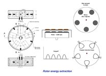
 

Attachments

  • Energy Extraction Suggestion.jpeg
    Energy Extraction Suggestion.jpeg
    252.9 KB · Views: 142

One query though, am I right in thinking that if the DC output from the rectifiers is put through a switch, and the switch is off, then the rotor will function as if there is no induction taking place with the magnets and coils? In other words, if a current in the coils is not permitted to flow then there will be no back emf to slow the rotor?

that is correct
 

I have done some calculations of the expected induced output voltage from typical coils and magnets which gives a value of about 0.1V and there are approximately 100-150 of these events every second. So I would expect to see a continuous DC voltage of 0.1V?

I’m struggling to come up with a means to usefully ’accumulate’ this energy so I can deliver it to a battery or a capacitor or show it doing anything at all.

By comparison the rotational energy of my rotor calculates at about 27J.

Any thoughts?
 

Hi,

Maybe your magnets arrangement is not optimal.
0.1V will not be enough to pass the rectifier (loss about 1.2V ... 2V depending on current), thus the rectifier output will be zero.

--> for a coil to produce voltage you need to "vary the magnetism" through the center of the coil. I don't know where your magnets have north and south.
So if all magnets "north" point to the coils you will get less output voltage than when the magnets are in north-south-north-south ... arrangement.

Another optimisation is when you give the magnetism a path through the coils and back. A loop.
This all already is known and optimized in an alternator and generator.
Maybe it's a good idea to do an internet search on how a generator / alternator works.


Klaus
 

Interesting points you make.

The proposed magnets are all North facing upwards towards the coils but can easily be alternated - best use 4 magnets for that with 5 coils.

My calculation was based on the emf generated by one coil as one pole of a magnet passes under it. Of course the magnet is not passing through the loop whereas in a normal generator the rotor spins within the stator coils so it’s certainly a different layout.

Im not clear how one can give the magnetism a path through the coils and back with my specific layout.
 

Hi,
best use 4 magnets for that
Yes, alternating directions with 5 magnets will become difficult ;-)
how one can give the magnetism a path through the coils and back
Mounting the 4 magnets on an Fe plate (opposite to coils) will cause 2 south and 2 north poles pointing to the plate. The plate thus is magnetically "neutral" but give a dedicated path from one magnet to the other magnets.
So the magnetism is focussed to the coiles side.

Similar Fe plate arrangement could be done in the coils side.
Here it's more difficult, because
* the plate needs enough distance to the magnets not to cause too much eddy current
* and you need to "force" the magnetism through the center of the coils.

Thus one can use 5 additional Fe cylinders, mounted in the center of each coil and mounted on the plate.
The "open ends" of the zylinders need to point to the magnets.

Klaus
 

Hi Klaus,

A ferromagnetic plate held above and parallel to the coil plate would be easier to achieve and I suppose will act a bit like a keeper to a bar magnet.

So you don’t mean magnets under the coils spinning and a Fe plate held above?

I will draw up the suggestion in Keynote to illustrate. I wish Fusion 360 would still work with my ageing Mac as I could create a 3D representation then as for earlier parts of my project. It’s a good reason to upgrade this year though 😊

Thank you for the input.

Jules
--- Updated ---

Klaus, do you mean alternate magnets on the rotor, a coil plate above that and an Fe plate above that?
 
Last edited:

Hi,

rotor - stator ... basically does not matter. For the wiring it´s easier when the magnets move.

so rotor = magnets
A big diameter Fe plate. 4 disc magnets, alternating, equidistant on a concetric diameter on the plate

Stator:
same big diameter plate. 5 Fe cylinders equidistant, on same concentric diameter mount on the plate.
. A coil around each cylinder

All similar to the right pictures of post#1

Klaus
 

Ok thanks. I’ll draw it up in 2D in due course and post.

To calculate I used EMF = - N BA/t but I recognise that the voltage will depend on the geometry of the setup and dA/dt. The arrangement you are suggesting has a much bigger value of that than my earlier suggestion.

Jules
 

Hi,

.. and for sure the coil winding count has influence on the output voltage.

efficiency:
let´s say the voltage drop across the rectifier is about 1.5V
and if one want´s this to cause less than 10% of wasted power, then the expected output voltage should be higher than 15V.

The less the output voltage the higher the percentual loss in the rectifier.

Klaus
 

Klaus, if I can get 15V I would be happy, especially as that is workable to charge a capacitor or a battery.

Let me interpret your suggestion in visual terms that will be easier to comment on.

Jules
--- Updated ---

Hi Klaus,

Here is my interpretation so far but there are a lot of variables to consider. E.g. should I keep the resistance of the coils down by using a larger diameter wire for the same number of turns? Does the thickness of the Fe cylinders make much difference?

Jules
 

Attachments

  • Energy Extraction 2.jpeg
    Energy Extraction 2.jpeg
    186 KB · Views: 67
Last edited:

how many turns per loop?
EMF is proportional to number of turns.
twice as many turns, twice the EMF
ten times, then ten times
and likley a little more I^2R loss, but less than the gain per turn
 

Hi,

Your drawing is wrong: (you built an eddy current brake. but no coil voltage)
--> The stator plate needs to be (far) away from the magnets.
--> The cylinders need to point to the magnets.

Stator plate + stator cylinders (with coils) | air gap | rotating magnets + rotating plate.

Klaus
 

It says how many on the graphic- 100
--- Updated ---

Hi,

Your drawing is wrong: (you built an eddy current brake. but no coil voltage)
--> The stator plate needs to be (far) away from the magnets.
--> The cylinders need to point to the magnets.

Stator plate + stator cylinders (with coils) | air gap | rotating magnets + rotating plate.

Klaus
So flip the stator plate upside down and increase air gap to say 1cm?
--- Updated ---

Hi Klaus,

So like this:

Energy Extraction 2.jpeg
 
Last edited:

Hi,
So flip the stator plate upside down
yes.

and increase air gap to say 1cm?
No. For good magnetic coupling = good efficiency, high voltage you need low air gap between magnets and cylinders.
But they must not touch for obvious reasons ;-)

To get low air gap but high distance of the plate (stator plate to moving magnets) you need a useful cylinder length.

Klaus
 

Ok if I increase the Fe cylinder height to 40mm and therefore the number of turns in the coils to say 400 that will increase the coil resistance by a factor of 4. So more voltage (Nx4) but less current (/4) due to increased R so perhaps the same Power? Perhaps there is a balance point or is it a try it and see how it performs situation?
 

Fe cylinders aren't well suited as magnetic core for AC fields, much of the power will be dissipated in eddy currents. That's why motors and transformers have laminated cores.
 

Sounds reasonable. I use Ferrite cores for my main solenoids which I imagine would be much better and can be found in many different formats.

If I used ferrite cylinders can I avoid using the Iron plates?

A bigger concern for me is actually the magnetic attraction between the disc rotor magnets and the cylinders and coils. The small Neo magnets are strong enough to pull the whole rotor off its bearing towards the fixed stator with its coils and cylinders. Also this attractive force will surely make the rotor hard to turn thereby preventing any induction in the first place.

Jules
 

Hi,

Ferrites surely are an improvement.
You still need the plates or any other material that is "magnetic conductive"
You may start with a bigger gap and see how it works.
If you are concerned about starting torque, then using 4 magnets instead of 5 was the right decision

We are developing from a "teaching model" to a serious machine now ;-)

Klaus
 

If the starting torque is too high or the rotor spin speed is reduced too much then the main function of the rotor (CEMF pulse investigation) will be impaired.

Plenty of variables to play with. If I got only 20% of the rotors energy I would consider that a positive result. 😊
 

Status
Not open for further replies.

Part and Inventory Search

Welcome to EDABoard.com

Sponsor

Back
Top