Continue to Site

Welcome to EDAboard.com

Welcome to our site! EDAboard.com is an international Electronics Discussion Forum focused on EDA software, circuits, schematics, books, theory, papers, asic, pld, 8051, DSP, Network, RF, Analog Design, PCB, Service Manuals... and a whole lot more! To participate you need to register. Registration is free. Click here to register now.

Extracting energy from a rotor

Status
Not open for further replies.

Kerrowman

Member level 4
Joined
Oct 12, 2021
Messages
75
Helped
0
Reputation
0
Reaction score
2
Trophy points
8
Location
West Penwith
Activity points
578
Hi all,

I’m looking to find an electronic way to extract the kinetic energy of a spinning rotor.

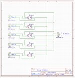
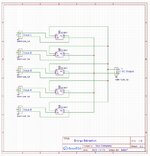
At the moment I have a rotor spinning at between 2,500-3,000 rpm driven by 5 solenoids that provide triggering for a FET that produces CEMF pulses of 800-1000V.

I’m able to harness the energy of the pulses and would also like to do the same for the rotor.

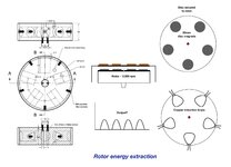
My idea so far is to have a set of 5 disc magnets secured to the top of the rotor (see pic) and which would spin under some configuration of pickup coils.

Assuming the induced voltage is an AC waveform this would need to be rectified to feed to a battery so I can’t imagine the circuitry would be that complicated.

I would appreciate any thoughts on the idea, the coil shape and configuration and the required circuit.

Thanks

Jules
 

Attachments

  • Energy Extraction Suggestion.jpeg
    Energy Extraction Suggestion.jpeg
    252.9 KB · Views: 141

staying within the bounds of your drawings:
your copper induction loops should have many turns.
this will increase the peak voltage.

each induction look will need its own full wave bridge rectifier

outside the bounds of your drawings:
you have an electrical source to drive the flywheel.
you want to build an electrical device to get electrical energy from the flywheel.

why go through the mechanical intermediate step?
build a circuit to go from the source you have to the output you want
 

I’m investigating the properties of high voltage CEMF spikes and open systems. The rotor energy is otherwise wasted but I’d like to see what I can extract.

Should my induction loops ideally be circular and if so would more loops of finer wire be better? If each output pulse from the loops is separate in time then can I not wire them in parallel via one FB rectifier or will that mess with their overall resistance to detrimental effect?

Thanks
 

Hi,

what you describe reminds me on a simple generator. Magnets and coils. M aybe in a different (looking) setup.

But if you want to charge a battery you should not do this with somehow uncontrolled pulses. If you rectify a pulse and feed it to a battery I expect high loss.
If you feed a 100V pulse to a 12V battery then about 88V or 88% of the energy is lost.
Thus you
* either need some storage element (inductor) between "pulse" and battery
* or control the voltage amplitude of the pulse. This could be done by replacing a fixed magnet with a variable electric magnet or by varying the distance between magnet and coil.

Read how an alternator in a car works.

Klaus
 

This experiment is just to see how much energy I can recycle from a rotor using inductive methods. My work on CEMF spikes uses the same device but is not about just feeding them to a battery.

I'm not concerned here with low efficiency or other offshoots to my question.

Returning to my query:

Should my induction loops ideally be circular and if so would more loops of finer wire be better? If each output pulse from the loops is separate in time then can I not wire them in parallel and use one rectifier or will that mess with their overall resistance to detrimental effect?
 

Hi,

I´m confused.
* you want to see how much energy you can recycle
* but you are not concerned about efficiency
In my eyes this is contradicting.

The rotational energy is 0.5 x I x w^2
w is the angular velocity
I is the moment of inertia
This is fix so far.

With 100% efficiency you can use 100% of this energy.
The lower the efficiency the less electrical energy you can use.

Klaus
 

the shape of the loop does not matter.
it is unclear what you mean by "use a finer wire" - what size wire were you planning to use?

the induced EMF depends on the area of the loop, the number of turns, the strength of the magnetic field, etc...
the actual output voltage will likely be small, mostly because the magnets you use will not have big magnetic fields
EMF = N (time rate of change of magnetic flux)

since magnetic field is fixed by magnets you use, and since the orientation between the loops and the magnetic field is fixed,
the only thing changing is the area of the loop inside the magnetic field, so EMF = NB (change in area of loop in magnetic field with time)
you'll need to do some experimenting to determine the output EMF

the symmetry of your drawing shows that all loops will be active at the same time
each loop will need its own FB, otherwise what happens in loop 1 is effected by loop 2.
you can connect the outputs in parallel

in post #4, Klaus is correct - you cannot just connect the output to a battery
in post #5, crutschow is correct - you will get less energy out than you put in
in post #7, Klaus is correct - the rotational energy is 0.5 * I * w^2.

it is impossible to get 100% efficiency
there will be losses for various reasons, starting with resistance in the wires and heating of any and all components.
 

I’m only interested in seeing what I can extract from a rotor and the technique of doing it to produce some useful DC to a battery.

The fact that it is not efficient etc is of no concern.

Consider it a demonstration of EM induction for a student that, via calculations, can show that perhaps only 50% of the rotor’s energy is converted to electricity and what factors might make that a bit more efficient.

I imagine using 0.5mm dia wire with say 50 turns per coil. Each coil will need a rectifier and so is the waveform I showed on my original graphic the likely output?

Thanks
 

Hi,

O.K. Understood. Good method teaching physics.

Just to be sure:
* you are aware that the voltage is proportional to the RPM?
* and that the RPM automatically will reduce (and the voltage, too)
* and thus there is maybe just a low range of RPM really useful to charge a battery directly.

******

Next level: How does the rectified output voltage look like when there are 5 coils and 4 magnets. ;-)
And what this means for the mechanical torque...

Klaus
 

Yes, as EMF is related to rate of cutting Mag field lines.

The field generated in the loops will tend to oppose the originating motion so I agree there will be a range of useful rpm. At the moment it runs at 2,700 to 3,000 rpm without any induction.

I will draw up a circuit in the next few days or so and post it here to see if I have the idea right.

I used to be a secondary science teacher but now retired I have grandchildren to inspire 😄 - and to see what I can recal 😳
 

Here is a quick schematic that I hope has all the necessary:

As for what happens with 5 coils and 4 magnets I'll need to wait till I open a Christmas cracker to find out! (Similar wave form shape but uneven spacing I guess - when rectified lower DC voltage with more ripple?)
 

Attachments

  • Energy Extraction Schematic.jpeg
    Energy Extraction Schematic.jpeg
    343.8 KB · Views: 80

Hi,
(Similar wave form shape but uneven spacing I guess - when rectified lower DC voltage with more ripple?)
I did not test it, but I expect:
when rectified: almost pure DC .. = almost no ripple

with 5 magnets and 5 coils:
all coil voltages are synchronous. 5 positive peaks, 5 negative peaks for one revolution.
after rectifier: 10 positive peaks per rev, voltage goes down to zero

with 4 magnets and 5 coils:
all the coil voltages are phase shifted: 5x (4 positive peaks, 4 negative peaks)
after rectifier: 40 positive peaks per rev, (same peak voltage as before), voltage "ripples" between 95% and 100% (just 5% ripple)
(all expectation for ohmic load and almost sine shape waveform. But in real live I expect a distorted waveform)

Torque becomes almost uniform.

*****

Klaus
--- Updated ---

added:

your schematic:

Rectifier: AC is input. + and - are outputs.
--> rectifier "-" and output "-" should be connected.

Klaus
 

Oooh, so a real advantage to out of phase induction and which I presume will be better for DC delivery to a battery?

Thanks

I knew I shouldn't have drawn the circuit too early :rolleyes:
 

Attachments

  • Energy Extraction Schematic.jpeg
    Energy Extraction Schematic.jpeg
    360.1 KB · Views: 70

Hi,

I did not test it, but I expect:
when rectified: almost pure DC .. = almost no ripple

with 5 magnets and 5 coils:
all coil voltages are synchronous. 5 positive peaks, 5 negative peaks for one revolution.
after rectifier: 10 positive peaks per rev, voltage goes down to zero

with 4 magnets and 5 coils:
all the coil voltages are phase shifted: 5x (4 positive peaks, 4 negative peaks)
after rectifier: 40 positive peaks per rev, (same peak voltage as before), voltage "ripples" between 95% and 100% (just 5% ripple)
(all expectation for ohmic load and almost sine shape waveform. But in real live I expect a distorted waveform)

Torque becomes almost uniform.

Klaus
not what i expected.
i see no reason to believe almost pure DC
since each magnet at each coil presents almost sin wave, for 5 magnets and 5 coils,
all the pulses are in phase, so i expect i would expect 2 pulse output with a gap and then 2 more pulses, etc.

i also expect no significant difference if you use 4 magnets instead of 5.
in this case, because there are 4 energized coils instead of 5, the peak EMF will be the same,
the repetition rate will be the same (assuming same rotation rate)
and it will still be repetitive 2 pulses and a gap.

you confused me with the pulse count for 4 magnets and 5 coils.
did you assume evenly spaced magnets and evenly spaced coils?
 

One query though, am I right in thinking that if the DC output from the rectifiers is put through a switch, and the switch is off, then the rotor will function as if there is no induction taking place with the magnets and coils? In other words, if a current in the coils is not permitted to flow then there will be no back emf to slow the rotor?
 

Status
Not open for further replies.

Part and Inventory Search

Welcome to EDABoard.com

Sponsor

Back
Top