motif
Newbie level 4
Hi All,
I am trying to get my scan key-pad working using RB (interrupt on change) but did not get any success.
Then I reduced the code to test single switch using only two pins RB3 and RB0. Also using external interrupt on RB0 (to get rid of port B reading and other issues with change-on-interrupt).
When I push the test-switch, the INTF flag in INTCON register is getting set, but some how the ISR is not getting called. Number of times I have checked the GIE and INTE bits (expecting if those are not getting set or getting overwritten somehow).
Also checked that RB0 value changes when switch is pressed.
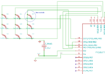
Attached is reduced code and schematic..
Kindly suggest any direction to trouble shoot this issue..
Here are more details..
Vcc : 3.30 V
micro-controller : PIC 16LF727
clock : Internal oscillator.
Compiler : CCS C version is V4.0
Thanks,
Sandy

Code:
#include <16LF727.h>

#FUSES NOWDT                 	//No Watch Dog Timer
#FUSES INTRC_IO              	//Internal RC Osc, no CLKOUT
#FUSES NOPUT                 	//No Power Up Timer
#FUSES NOPROTECT             	//Code not protected from reading
#FUSES NOBROWNOUT            	//No brownout reset

#define delay_val 5
#use delay(clock=8000000)


#define mydelay1 5
#byte ANSELA = 0x185
#byte ANSELB = 0x186
#byte TRISB  = 0x86
#byte IOCB   = 0x96
#byte WPUB   = 0x95
#byte INTCON = 0xB
#byte PortB  = 0x06
#byte OPTION_REGISTER = 0x181

//### Debug LEDs
#define GREEN_LED PIN_A6
#define RED_LED   PIN_A7

//### ISR method
#int_ext
void int_ext_isr(void)
{
//### glow red led to check if isr executed.
output_bit(RED_LED, 0);
INTCON = 0b10010000;
}


void main()
{
// ### turn off debug LEDs
output_bit (GREEN_LED, 1);
output_bit (RED_LED, 1);

//### Port A Digital-IO
ANSELA = 0x00;

//### Port B Digital-IO
ANSELB = 0x00;

//### port B input/output configuration, port B3 output, rest input.
TRISB = 0b11110111;

//### option register, Week pull up enabled
OPTION_REGISTER = 0b01111111;

//### weak pull-up for RB0 enabled
WPUB =  0b00000001;

//### Drive B3 to low
output_bit(PIN_B3,0);

//### interrupt control, set Global GIE and INTE
INTCON = 0b10010000;

delay_ms(50);


while(1)
{
output_bit (GREEN_LED, 0);
delay_ms(500);
}
}
Last edited: