Continue to Site

Welcome to EDAboard.com

Welcome to our site! EDAboard.com is an international Electronics Discussion Forum focused on EDA software, circuits, schematics, books, theory, papers, asic, pld, 8051, DSP, Network, RF, Analog Design, PCB, Service Manuals... and a whole lot more! To participate you need to register. Registration is free. Click here to register now.

Explorer16 PIC24F board SPI interface write.

Status
Not open for further replies.
That looks better. I think you may not be getting the best out of the logic analyser - I looked up the specification and it can sample at 25MHz.

Keith

Thanks Keith..Now, I am getting good output. But still have problem with CS line. Check below pic. It goes high before 5 byte transfer. Any clue? 20120604_104846.jpg
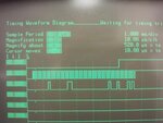
The B0 supposed to go high after compete transfer. But it won't.
 

Have you checked the errata for the chip you are using? Microchip have a lot of problems with SPI. I needed to use 16 bit framed mode receive on a PIC24H and it simply doesn't work. I needed to use a work round described in the errata.

Keith

- - - Updated - - -

Also, in your code are you sure you are waiting until one byte has been sent before you send another? Try single bytes and then multiple bytes with a deliberate delay between bytes.

Keith
 
I dont know iof it's relevant (sorry about any errant posts) but I use this on the 16f to make sure the byte've all gone, I bet there's an equivalent on the 24f but I write my own SPIOut (on my 24FJ setups) because of using several dat lines with one clock (The SPI LED matrix's I send a bit to 4 panels at once) and haven't looked deeper....

[code snippet]
void SPI_DataSend(const unsigned char data)
{
SSPBUF=data;
while(!SSPIF) ;
SSPIF=0;
}

[/code snippet]
Cool :)
NEAL
 

lol, I'd have read that as RecieveBufferFull at 1st glance, glad to be "steered", if it ever comes up I'll know now, cool! XD
NEAL

On the 16 the flag has to be cleared too, especially as interupt-driven
 

Yes, mine are interrupt driven and I have an interrupt flag clear. The PIC24 SPI is a bit confusing I find (probably the same as the rest of the Microchip SPI interfaces) in that I would have expected separate read & write buffers!

Keith.
 
I think I'd been using SPITBF, Transmit buffer full, but even then that's only relevent in non-enhanced, I realise why I had trouble with this now, it is only the buffer filling that sets the flag, not transfer complete... There are separate recieve and transmit buffers on the 24FJ64's, my current reference PIC, I'm not sure waiting for the recieve buffer to have spare places is going to cause a delay in writing (while(!spi1rbf);) unless reads are involved, SPIRBF does seem backwards! :)
NEAL

Sorry, but what about while(!SPIxSTATbits.SRMPT), I might just have a test for fun
NEAL
 
Last edited:

There is no SRMPT on the PIC24H but looking at it on the PIC24F it looks useful! The reason I ended up using the receive buffer to detect when data has been sent is that the transmit flags on the PIC24H only tell you the buffer is empty (it is double buffered) so you can load more data. It doesn't tell you it has been sent. However, the transmitted data ends up in the receive buffer so when the receive buffer is full the data has been transmitted. That is how I remember it anyway - it is a while since i looked at that code.

Keith.
 
However, the transmitted data ends up in the receive buffer so when the receive buffer is full the data has been transmitted. That is how I remember it anyway - it is a while since i looked at that code.
I do love to hear *real world* experience, always a pleasure mate, when it's been done for real and working I know it's tested! I will have a quick re-visit on the SPI-MRF24 rf modules now this has sparked some ideas!

This one nugget of info may be massively relevant to me one day, I send *massive* thanks, ta matey! XD When google looks back in 2000000^n years, wondering about it's "creators" (2nd Millenium humans!) it'll see that's how humans best worked things out, using keyboards and logic!!!

Neal :-D
 

The worst part is the amount of time you spend getting round bugs in firmware. I was trying to talk to another board being made by someone else using an FTDI chip. He had problems with the FTDI chip which turned out to be a firmware bug so we couldn't use the modes we had originally planned. Then I found that framed receive didn't work on the PIC24H due to a firmware bug so I had to use a work round which involves setting the chip select as an interrupt (with SPI disabled) and when you get the interrupt, enable the SPI and after the reception, disable SPI again and re-enable the interrupt. It all works but slowed down the software a little which was annoying as the whole point of using the PCI24H was for speed. The software was time critical and I could have done without the extra code to do what should have been done in the hardware. :x

Keith.
 
I *like* the workaround, it'll stay in my back-memory-stores I am sure it'll be used at some point.. A very logical way to sort a small problem, COOL indeed...!
NEAL
 

Guys...Now I am getting my SPI output perfectly with CS line too. I have changed spi right code to
Code:
unsigned char WriteSPI1(unsigned char Data)
{

    // Wait for a data byte reception
    while(SPISTATbits.SPITBF);
    SPIBUF = Data;
	while(!SPISTATbits.SPIRBF);
	Data = SPIBUF;
	return 0;

}

Anyway...I have tried SPI interrupt but it won't work at all on board or in simulator. My problem has been solved but still curious about the SPI interrupt configuration. I didn't find much information about it in datasheet. Any experience with SPI interrupt?
 

Brilliant!! I am so glad, to have been part of working this out I'll remember this for a long time, many thanks!!

Cool, this is why I love discussion, real world experience counts!! :)
Thanks EDA, and thanks Parthiv2eng & Kieth, superb mate(s)!
NEAL
 

My SPI interface writes based on a timer interrupt, not an interrupt from the SPI. The reading is interrupt driven. This is the basic code:

Code:
void _ISR _NOPSV _SPI1Interrupt(void) 
{
	if (SPI1STATbits.SPIROV) overflow++;
	
	SPIdat[SPIcount] = SPI1BUF;  // always read the data

// other code here

	_SPI1IF = 0;	// clear SPI interrupt
}

However, due to the previopusly mentioned firmaware bug on the version of PIC24H I also needed to use change notification interrupt to emulate the framed mode:

Code:
void _ISR _NOPSV _CNInterrupt(void) 
{
	if ((PORTB & 0x0004) == 0) {
		SPI1STATbits.SPIEN = 1;  // enable SPI
		IEC0bits.SPI1IE = 1; //Enable The Interrupt
	} else {
		SPI1STATbits.SPIEN = 0; // disable SPI
		IEC0bits.SPI1IE = 0; //disable The Interrupt
		_SPI1IF = 0;
	}	
	_CNIF = 0;	// clear CN interrupt
}

It may be different on the PIC24F

Keith.
 

Ah, on the change notification, superb! I had considered an inter-chip serial-data-transfer method *very* similar (a year ago!), <<ing another pin's value to read clocked serial, but thankfully BigDog "steered" me towards SPI and I2c... I do love "stuff" like this, especially real code, hopefully I'll check "it" with a 24F device to device when I get a chance to add to the thread, but for today I am busy "Rs232al-ize"ing a 9 panel SPI matrix text/effects/graphics controller ready for a demo tomorrow!

Cool Kieth&Parthiv, appreciated
NEAL
 

Status
Not open for further replies.

Similar threads

Part and Inventory Search

Welcome to EDABoard.com

Sponsor

Back
Top