Continue to Site

Welcome to EDAboard.com

Welcome to our site! EDAboard.com is an international Electronics Discussion Forum focused on EDA software, circuits, schematics, books, theory, papers, asic, pld, 8051, DSP, Network, RF, Analog Design, PCB, Service Manuals... and a whole lot more! To participate you need to register. Registration is free. Click here to register now.

excitation of inverted f antenna using hfss

Status
Not open for further replies.

ljx1067

Junior Member level 1
Joined
Mar 30, 2008
Messages
16
Helped
0
Reputation
0
Reaction score
0
Trophy points
1,281
Activity points
1,382
inverted f antenna hfss example

71_1215959467.jpg


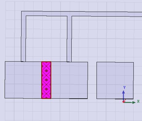
the red part is the lumped port in my simulation ,is this right? from s11 it seems that the impedance matching badly from 10G until 100GHz.
thanks.

Added after 1 hours 18 minutes:

this antenna is proposed to use in cmos circuit,the invert f part is small.so three pads are added for measurement. the middle pad is for singnal of GSG probe and the other two pads for ground.
I think the lumped port should be from ground to signal so I draw a rectangle between them,is that right?
 

I guess you need to move your port to the position where you really excite your IFA. Please take a look at the position shown in the figure. Moreover, I've attached a real world example in the doc file.

regards,
shameem
 

thanks for ur answer. I know that a port should be put in where u said,but I donnot know how to set it in the HFss,can u explain it ?

I connect a bond wire between the two ground pads and there is resonance now,however,the resonance frequency is changing with the diameter of the bond wire.Is there any restriction about bondwire's size?
 

ljx1067 said:
thanks for ur answer. I know that a port should be put in where u said,but I donnot know how to set it in the HFss,can u explain it ?

remove some rectangular portion of copper from the ground pad just under the feed point of IFA. replace that part with a rectangular surface (as you did it earlier) to define your port.
 

I tried the way u said but still not right. I think that it is because the middle pad is not a ground pad but a signal pad. a lumped port should be drawn connecting signal part and ground part.

however,I still donnot know how to solve this.
 

ljx1067 said:
I tried the way u said but still not right. I think that it is because the middle pad is not a ground pad but a signal pad. a lumped port should be drawn connecting signal part and ground part.

you are right. I'm very sorry that I didn't read your first post carefully to find out that your middle pad isn't gnd.

Now the point is: since your application is for very high frequency, addition of such pad change the size/resonant behaviour of the overall IFA that may not be intended. May I ask, what is your expected bandwidth/frequency range?

Regards,
shameemkabir
 

U are right,the freq is 60GHz,here I send the paper I followed.
 

As far as I know, resonance behaviour of IFA largely depends on the ground plane size. I didn't find any reference of ground plane (except the ground pad) in this paper (I'm not familiar with IC technology). you do have two ground pads here. why do you need two? (I didn't understand from the paper).

It would be worth looking at your .hfss file. Would you please send that!
 

shameemkabir said:
As far as I know, resonance behaviour of IFA largely depends on the ground plane size. I didn't find any reference of ground plane (except the ground pad) in this paper (I'm not familiar with IC technology). you do have two ground pads here. why do you need two? (I didn't understand from the paper).

It would be worth looking at your .hfss file. Would you please send that!

here is my hfss model. the three pads are used to connect the GSG(ground signal ground) probe. I find a paper talking about how to set the port of GSG probe as I made in the model.However,I cannot get the same result with the paper.the paper's result is get from IE3D.
 

I am simulating the same inverted-F antenna now. I don't know how to set the lumped port,too. Have you had the correct result later? Can you help me, please?
 
For how to set up a GSG probe in HFSS, see the first attached file at
 

Status
Not open for further replies.

Part and Inventory Search

Welcome to EDABoard.com

Sponsor

Back
Top