Continue to Site

Welcome to EDAboard.com

Welcome to our site! EDAboard.com is an international Electronics Discussion Forum focused on EDA software, circuits, schematics, books, theory, papers, asic, pld, 8051, DSP, Network, RF, Analog Design, PCB, Service Manuals... and a whole lot more! To participate you need to register. Registration is free. Click here to register now.

Excitation for hemispherical helix

Status
Not open for further replies.

rawrster

Newbie level 3
Joined
Jul 23, 2013
Messages
4
Helped
0
Reputation
0
Reaction score
0
Trophy points
1
Activity points
31
Hi all.

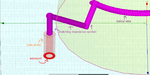
I am trying to simulate this hemispherical helical antenna with an integrated matching section wire and when I compare the results I've obtained to the actual results, my results are wrong. I have a suspicion that the waveport / excitation could be the incorrect design for antennas with this type of structure.

I have tried, waveports with a PEC backed cap,
waveports/lumped ports with integration line defined,
and currently, Coax probe waveports.

I have also tried to use voltage excitations with the PEC backed cap, but to no avail.

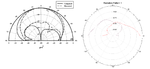
The radiation patterns obtained from those attempts are all mostly incorrect, as shown in the attached figures.

Can anyone please help me with the selection of the excitation?
Thank you so much for your time and consideration.
 

Attachments

  • hemihelix1.rar
    101.9 KB · Views: 55
  • antenna.png
    antenna.png
    155.2 KB · Views: 67
  • antenna1.png
    antenna1.png
    162 KB · Views: 57
Last edited:

What simulator are you using? Why do you suspect the excitation method? Is it possible to apply an "ideal" excitation? How were the "actual" results measured?
 

HFSS 13.
By using different ports the radiation pattern varied. Currently trying lump port on rectangular sheet.
If there was a way, I would like to know.
The actual results antenna was excited using a delta gap voltage source.
 

Where is the earth, relative to the antenna, and how is it simulated (ideal, or particular soil type, or ?)? And is there any ground plane or counterpoise or ground element associated with the antenna?

To better-match the actual measurements, you would need to simulate with the earth/ground types and placements as they were when the actual measurements were obtained.

And perhaps you can (and maybe should) model the coax or whatever feed type was used, and the connector that was used, and the signal source characteristics at the other end of the feed.
 

The ground plane is PEC, where the hemisphere sits on.
I am simulating the antenna based on the image of the antenna that is in the journal paper itself.

I do not follow what you mean by signal source characteristics though. What do you mean by that?

Thank you and regards.
 

Regarding the source and feed: it depends how they did it in the paper you are trying to match the results to. If there was a coaxial cable or other type of transmission medium connecting an RF source to the antenna, maybe the characteristics of all of that could matter. But I didn't realize that you were working from a journal photo so you already know how it was configured. The complex impedance of the feed should match what was actually used.

It wouldn't matter, here, but when comparing two different antennas, for example, you do need to also model the feed line, since it could change the VSWR, with a different antenna configuration.
 

hw1.png

The actual antenna looks like that. I'm thinking, perhaps a normal feed wire underneath the ground plane?
*There are two types of geometry, one for 2 layered substrate, one for single layered. Currently attempting single layered substrate*
 

Status
Not open for further replies.

Part and Inventory Search

Welcome to EDABoard.com

Sponsor

Back
Top