pgr2002
Member level 5
- Joined
- Aug 1, 2013
- Messages
- 87
- Helped
- 0
- Reputation
- 0
- Reaction score
- 0
- Trophy points
- 1,286
- Location
- Hyderabad, India
- Activity points
- 2,015
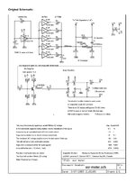
I built this yorkie's ESR meter which is working as described. Can anyone tell me how to modify this circuit to include an LED to display when a capacitor is tested and is found to be shorted. I attach this diagram.