Continue to Site

Welcome to EDAboard.com

Welcome to our site! EDAboard.com is an international Electronics Discussion Forum focused on EDA software, circuits, schematics, books, theory, papers, asic, pld, 8051, DSP, Network, RF, Analog Design, PCB, Service Manuals... and a whole lot more! To participate you need to register. Registration is free. Click here to register now.

ESD protection

Status
Not open for further replies.

Rajinder1268

Full Member level 3
Joined
Mar 20, 2021
Messages
162
Helped
1
Reputation
2
Reaction score
4
Trophy points
18
Activity points
1,228
Hi all,

I have a circuit which is powered from 12V car battery. The circuit keeps getting destroyed it has a regulator 5V and opamp. How can I protect this from transients, which I assume is damaging the electronics. Is a TVS diode a good solution?
How would I select one?
Thanks in advance
 

Hi,

A one and a half line text is not suitable to describe the situation.
To answer your question we need to get more details.
* schematic
* wiring
* PCB layout
* error description: when and how it fails. What devices become defective, (isolatiing, conductive, exploding....)
Pictures, photos, documents, are good informations for detailed discussion.

A TVS diode may work or not.
A TVS diode will become low ohmic on high voltage. Now it depends on series resistance, timing, current...whether it can safely protect your device ... or in worst case will explode on it's own and cause more damage than without a TVS.

When an electronic device gets defective there are mainly three reasons:
* overvoltage. Even very short pulses (less than 1 microsecond) may cause damage. And fail, either immediate or after years. Often as "conductive fail".
* overcurrent. Short pulses in the milliseconds may destroy bonding wires. Often causes immediate "open fail"
* overheating: long term overload, high ambient temperature. Usually visible destruction.

Klaus
Hi thanks for your reply.
I will post up a schematic to highlight the issue.
A car battery is used through a fuse, this is used to power up a few circuits. One is a relay (MOS-type). This is the device that is blowing as it switches the 'raw' car voltage through the rest of the circuit.

I will post what I have in a few minutes.
any help would be appreciated.

Thanks in advance.
 

Yes, we dont know if the damage is from
1..overvoltage spikes
2...ESD
3....Short circuit on output.
4....Misconnection.

What happens when you run the same circuit on a stable 12v lab power supply?...does it work OK then?
--- Updated ---

But if it is transient overvoltages...then you could always add in a series fet switch, and a comparator, and switch your circuit out whenever a transient arrives...also combine this with a TVS because the comparator will not react immediately.
 
Hi, The supply from the battery is switched by a MOS relay i.e. AQY212S, this is driven by a Microcontroller. It is this that is getting damaged, it has a max load voltage of 60V, so i believe there is a inductive spike that is destroying this device and hence I am not getting supply to the rest of my circuit. The current through this device is around 50mA max.
 

If the failure is from the starter voltage transient, you could add a small series resistor, along with a large capacitor and TVS or Zener to ground.
How much current does your circuit take?

Alternately, can you connect the circuit to the ignition switch auxiliary output, which is turned off during the starter period?
Hi,
The current is 50mA not more than that. I was thinking of using back to back zeners, would that work to limit the voltage to say 14.6V or something similar? I will post a image of what I mean. Are you saying a large capacitor and zener in parallel?

Thanks in advance.
 

A schematic would be most helpful.

Do you only use the 12 V battery, or is it an actual automotive application, where quite a wide voltage range can be expeced at the 12 V line due to cold-crank and load-dump events [1].

[1] https://www.ti.com/lit/an/snva681a/snva681a.pdf?ts=1616189384959

BR
Hi, it is an automotive application, so 12V car battery, yes you are correct there is possibly a wide range 9.6V to 14.4V at least i.e. low battery and charging.
Could I use back to back zener diodes to clamp the voltage, the current is only 50mA. I have attached a diagram of what I think. The lower zener could be 14V and the upper would only conduct leaving a drop of 0.6V, so restrict the output to 14.6V (or something similar).
 

Attachments

  • IMG_20210320_160934.jpg
    IMG_20210320_160934.jpg
    1.7 MB · Views: 61

I do not have PCB space to fit large components. So was looking for a simple solution with minimum components.
 

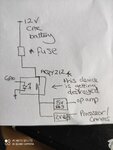
Hi all, here is a block diagram of the circuit. The AQY212 is getting destroyed, I believe it is due to inductive transients. This device is rated at 60V load max, so the transient must be greater than this.

My options are :
Low pass filter
TVS or back to back zeners.

Any help would be appreciated.
Thanks in advance
 

Attachments

  • IMG_20210321_115201.jpg
    IMG_20210321_115201.jpg
    1.5 MB · Views: 84

Hi,

please have a look at Fig. 4 in the document I linked in reply #11, where you can see different over/under voltage events which are common on a 12 V rail in an automotive environment. Starting on page 21 they are showing power rail protection including calculation examples, elaborating how to choose a proper TVS.

In my oppinion at least an unidirectional TVS would be required. Which one is suitable, you have to determine by your own, as you have to consider required board space, cost and do not forget the derating caused by the ambient temperature. You migth also consider the use of a varistor to limit the inrush current when turning on the PhotoMOS, as mentioned on page 14 in the datasheet of the AQY212.

BTW, does your circuitry fail in the lab when powered by a benchtop power supply as well?

BR
 
Hi,

In your case a simple overvoltage protection, even unipolar (zener), could be sufficient, because the current is limited.

Klaus
 
Hi,

please have a look at Fig. 4 in the document I linked in reply #11, where you can see different over/under voltage events which are common on a 12 V rail in an automotive environment. Starting on page 21 they are showing power rail protection including calculation examples, elaborating how to choose a proper TVS.

In my oppinion at least an unidirectional TVS would be required. Which one is suitable, you have to determine by your own, as you have to consider required board space, cost and do not forget the derating caused by the ambient temperature. You migth also consider the use of a varistor to limit the inrush current when turning on the PhotoMOS, as mentioned on page 14 in the datasheet of the AQY212.

BTW, does your circuitry fail in the lab when powered by a benchtop power supply as well?

BR
Thanks for the reply,much appreciated. I was thinking of a unidirectional TVS, I will have a look at the info you suggested. Is it ok to post my results?
--- Updated ---

Hi,

In your case a simple overvoltage protection, even unipolar (zener), could be sufficient, because the current is limited.

Klaus
Hi, thanks for your reply. So just a say for example 15V zener would be sufficient?
--- Updated ---

Hi,

please have a look at Fig. 4 in the document I linked in reply #11, where you can see different over/under voltage events which are common on a 12 V rail in an automotive environment. Starting on page 21 they are showing power rail protection including calculation examples, elaborating how to choose a proper TVS.

In my oppinion at least an unidirectional TVS would be required. Which one is suitable, you have to determine by your own, as you have to consider required board space, cost and do not forget the derating caused by the ambient temperature. You migth also consider the use of a varistor to limit the inrush current when turning on the PhotoMOS, as mentioned on page 14 in the datasheet of the AQY212.

BTW, does your circuitry fail in the lab when powered by a benchtop power supply as well?

BR
Hi,
I will try it on a bench supply, however it is intended use is with a car battery. But I think that would be a good test.
 
Last edited:

Hi @KlausST,

... even unipolar (zener), could be sufficient, because the current is limited.

I would agree with the unipolar solution, but how is the current limited in your opinion? The current is "given" by the actual transient event, and when the zener voltage is exceeded there isn't any series element (except inductance due to the wiring) limiting the current through the zener diode. So in my opinion the zener will dissipate also quite a high amount of power.

As far as I know an unidirectional TVS is a "high-power" version of a zener diode, designed to supress fast transients events. Where zener diods are designed for voltage regulation purposes. Thus, TVS diods have a fast response time. Please correct me if I'm wrong.

BR
 

Hi all, thanks for your replies and useful help. Would the best way to check the circuit is to apply more than 60V for the car battery? Or do I check in a ESD environment i.e. test house for ESD?
Thanks in advance
 

Hi,
I would agree with the unipolar solution, but how is the current limited in your opinion? The current is "given" by the actual transient event, and when the zener voltage is exceeded there isn't any series element (except inductance due to the wiring) limiting the current through the zener diode. So in my opinion the zener will dissipate also quite a high amount of power.
My guess (don't know for sure) that the voltage comes from stray inductance when switching OFF the load.

Maybe there is an external source of this voltage... then there should be an information. Should we expect a power burst or ESD ? HBM MM?

Just want to notice: I realized that the headline talks about ESD....but how dies ESD come to this signal path?

Klaus
 
Last edited:

Hi ,

... headline talks about ESD.

yes, considering only ESD I totally agree, regarding the limited current. Nevertheless, as the OP uses the circuitry in an actual automotive environment I would expect high energetic tranients as well. Here my question is how he has tested the circuitry so far...

I will try it on a bench supply, however it is intended use is with a car battery. But I think that would be a good test.

Does this mean you have it tested with a 12 V battery in the lab, or only directly within a car?

BR
 
Status
Not open for further replies.

Part and Inventory Search

Welcome to EDABoard.com

Sponsor

Back
Top