Continue to Site

Welcome to EDAboard.com

Welcome to our site! EDAboard.com is an international Electronics Discussion Forum focused on EDA software, circuits, schematics, books, theory, papers, asic, pld, 8051, DSP, Network, RF, Analog Design, PCB, Service Manuals... and a whole lot more! To participate you need to register. Registration is free. Click here to register now.

[SOLVED] ESD issue on 1602 LCD

Status
Not open for further replies.

jishnuprakash

Junior Member level 2
Joined
Feb 21, 2022
Messages
22
Helped
0
Reputation
0
Reaction score
0
Trophy points
1
Activity points
144
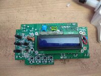
I am facing a problem with 1602 LCD while testing for EMI EMC compliance of our design, we are using a 1602 LCD with PCF8574
controlling with I2C, when applied ESD air 4KV the display goes gibberish, the microcontroller board is working fine,
I have to restart board to solve this problem, we are using a BLAZE display , we have TVS diodes place in data line, we also have a RH+T sensor on the
I2c line as well
 

I don't know your spec regime but to me, the ESD test
is a "survive" test and not a "perform unperturbed" one.
You ought to be sure that -you- know your spec regime,
and aren't assuming an undue burden.

But if you need to fix this lockup, there's some things to
look at.

TVS diodes on data lines, can just mean the ground or
your local branch of it, gets jacked when the ESD impulse
hits it. Digital guy's "ground" is not power guy's ground
and what your abnormal conditions do to signal offsets
has to be somebody's guess.

You can fix the base response or you canfix the symptom.
You say power cycling works, so maybe a wee bit of code
that polls the display, hard, every few frames could make
recovery "self-righting" enough. Maybe there's a strobe
that could be applied to a reset line, for free (-ish, if a
board or harness rev is already teeing up).

You could make yourself a fault injector with pulse generator
and passives, and try to emulate the ESD response; at least
get to a narrower list of "could be" threat-path scenarios.
 

Is your display a piggy back I2C module on backside of display, which has its own controller
in it ? Like this -

1649152302016.png


Problem may be on main LCD board under black blob is another controller IC subject to
pickup and a LCD interface part. If so what you may have to do is R/W display looking for
a specific response, and if you dont get it either cycle its power and/or invoke its reset pin.

The controller in the LCD is often a 44780 or derivative, Hitachi, now Renesas. There you
can find its commands.


Regards, Dana.
 

Is your display a piggy back I2C module on backside of display, which has its own controller
in it ? Like this -

View attachment 175267

Problem may be on main LCD board under black blob is another controller IC subject to
pickup and a LCD interface part. If so what you may have to do is R/W display looking for
a specific response, and if you dont get it either cycle its power and/or invoke its reset pin.


Regards, Dana.
yes this is the display I am using, i will try this solution, but do you have any hardware solution, if the board resets we can pass only in criteria B to pass in criteria A, we need no problem while ESD strike
 

Hi,
thanks for reply, we are using 4 wires to connect lcd from pcb , lcd is mounted over pcb using screws

I´m sorry, a textual descrition can´t tell how solid the groundplane is made and how the traces are routed, trace lenghts, current flow....

A picture tells more than a lot fo words.

Klaus
 

Hi,


I´m sorry, a textual descrition can´t tell how solid the groundplane is made and how the traces are routed, trace lenghts, current flow....

A picture tells more than a lot fo words.

Klaus
02-181-009 TC3_MB_V5 DSN-I2c conn.jpg

this the connection to LCD, from this connector i take four wires to back of lcd,
 

Can you use a DSO oscilloscope, set up its trigger for ESD like event (eg. HV pulse), and probe
each line seeing where you get a trigger, eg. a trigger << Vss or >> Vdd on supply or ground or
data lines. Probe ground crucially short. To try to find the susceptible pin.

The other investigation is set up a 50 ohm jig and test the diodes and zeners for switching speed,
to make sure they are reasonably fast. Use a fast Tr/Tf time pulse generator to drive jig. Short leads
both in prototype and jig and scope probing. nH of L matter.


Also consider using .001 and / or .01 uf ceramic disk caps on LCD display power pin, choose a cap
with low L and "stiff" pins, eg diameter, to get low stray L and ESR. Pay attemtion to cap datasheet,
not all vendors have same esr and low L performance. Fat short pins like this -

1649157100324.png


Regards, Dana.
 
Last edited:

If you really have 10nF capacitors from both I2C lines to ground it is likely you have marginal logic levels to start with. Remove them, or replace them with much smaller values if high frequencies are present, maybe 100pF or smaller.

Brian.
 

thank you all i shall try these remedies you suggested, i also have one question if LCD we used has ESD rating 8KV air discharge and 4KV contact discharge can this problem be solved, or dose attachment board also need to have that rating ?
 

ESD rating of the display isn't actually connected to the thread topic. It describes withstand to ESD damage when striking the device terminals, determined in unpowered state. I presume, you are not exposing the display signal and power lines directly to ESD.

Function loss during ESD exposure of certain instrument parts is a completely different topic. As already mentioned in post #4, EMC rules are fulfilled if the instrument performs a self-recover from ESD induced faults. In case of a LCD display, either a periodical re-initialization (worse) or detection of configuration and content corruption and conditional re-initialization (preferred) can do the trick.

The measures discussed so far in this thread are not not reliably preventing I2C data corruption and respectively not securing against corrupted display content, configuration loss or display reset.

Data corruption occurs at interface voltage levels far below ESD ratings or even clamp level of protection devices.
 

hi,
I have tried some solutions you suggested, I grounded the LCD metal frame as instructed from LCD manufacture which helped increasing ESD immunity to +/- 6KV which is not enough as it need to have EMC up to +/-8KV
 

Hi,

Still no wiring picture no PCB layout picture (I did not ask about a schematic).

Klaus
 

Hi,

Still no wiring picture no PCB layout picture (I did not ask about a schematic).

Klaus
hi,
the cable covered in copper foil are the once used for data,
 

Attachments

  • IMG_20220426_114326.jpg
    IMG_20220426_114326.jpg
    14.7 MB · Views: 136
  • IMG_20220426_114334.jpg
    IMG_20220426_114334.jpg
    12.7 MB · Views: 132
  • IMG_20220426_114338.jpg
    IMG_20220426_114338.jpg
    13.2 MB · Views: 132
  • IMG_20220426_114344.jpg
    IMG_20220426_114344.jpg
    13.7 MB · Views: 126
  • bottom.jpg
    bottom.jpg
    685.4 KB · Views: 142
  • SILK_BOT.jpg
    SILK_BOT.jpg
    637.2 KB · Views: 125
  • SILK_TOP.jpg
    SILK_TOP.jpg
    493.1 KB · Views: 140
  • TOP.jpg
    TOP.jpg
    720.3 KB · Views: 120

Hi,

Thanks for the photos. We now see that the wiring is short and straight.
Some issues:
* there now are three parts involved. The main board, the I2C-parallel board and the display.
you say that the mainboard is working fine. How did you test this? - I mean the correct data transfer to the display. Do you have a logic analyzer or a scope?
Can you be sure that the I2C-parallel board is working fine?
Did you try a "reconfiguration" of the display (this can only work if mainboard and I2C board is working correctly.
* also we see that you don´t use a really solid GND plane. In case of ESD, EMI/EMC problems this is one of my first things to check. A copper fill is not to compare with a solid GND plane regarding HF behaviour (what an ESD pulse is)

What we don´t see:
How the whole circuit is mounted in the case. Is it a metal case or plastic?
How and where exactly the ESD gun is connected (both: tip and GND) .. to recognize the ESD current path.
If there is a plastic (acryl glass) in front of the display.

Klaus
hi,
thanks for the reply
1) Main board has valves as output and it will be turning on and off according to its timing,
so even when the display shows gibberish the valve controls works as per timing.
2) I have enabled WDT for the controller hence if I2C bus is stuck the board will reset
During the 8KV testing at the first pulse then at the second pulse the display turns gibberish
but main board (valve operation) works normally
3) No, I am not sure if I2C-Parellel Board works fine, I bought it from a online site named ROBU
4) the circuit is mounted on a plastic case, connected using metal screws
5) Test fails in ESD AIR not Contact, a sticker comes above LCD display ,and entire assembly has no metal part outside
 

HI,
any suggestions , about my issue or shall I consider this unsolvable and go with 6KV as my product STD
 

Status
Not open for further replies.

Part and Inventory Search

Welcome to EDABoard.com

Sponsor

Back
Top