Continue to Site

Welcome to EDAboard.com

Welcome to our site! EDAboard.com is an international Electronics Discussion Forum focused on EDA software, circuits, schematics, books, theory, papers, asic, pld, 8051, DSP, Network, RF, Analog Design, PCB, Service Manuals... and a whole lot more! To participate you need to register. Registration is free. Click here to register now.

Error Amplifier in PWM based DC-DC converters

Status
Not open for further replies.

viperpaki007

Full Member level 5
Joined
Jul 2, 2008
Messages
270
Helped
11
Reputation
22
Reaction score
8
Trophy points
1,298
Location
Finland
Activity points
3,395
Hi,

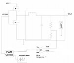
Can somebody tell me what is the difference between error amplifier and and a comparator. Which one i should use in the feedback PWM generation loop of DC-DC converter. (See figure attached).

If i use a comparator to compare Vref and Vout, comparator output can only be either VCC or VEE. It will not make a variable duty cycle waveform to control the DC-DC converter. I need some other kind of circuit like Error amplifier but i am not sure what is the output of error amplifier and why it is different from comparator.

Looking forward for your comments
 

Attachments

  • Error_amp.jpg
    Error_amp.jpg
    50.5 KB · Views: 176

Probably i can rephrase my question. What is the difference between and error amplifier and a comparator? what is the output of error amplifier compared to comparator?
 

error amplifier is just an differential operational amplifier. comparator is just a level comparison hardware i.e. if input voltage is below some value, o/p is zero, otherwise ouput is Vcc.
By differential operational amplifier means, the op-amp in differential amplifier mode, the error signal is generally comparison of two voltages which is applied to two inputs of op-amp, op-amp will cancel out the common mode voltage and will amplify the difference of two.
According to ur circuit, the output of EA is the difference between Vref and Vout, its circuit where u want Vout = Vref. So, the error signal is amplified and sent to PWM control to increase or decrease duty cycle of PWM to increase or decrease the average voltage.
Find current sense circuits on google, u will get better idea of error amplifiers.
 

Hi ashugtiwari,

As far as i know comparator output is also equal to difference of input voltages multiplied by very large gain. Then why error amplifier becomes different from comparator?.
 

U said that. U already know the difference between comparator and op-amp. Any op-amp can be configured as comparator by just using it as open loop amplifier or positive feedback amplifier to drive its o/p stage to either on or off.
Now error amplifier is a very small signal open loop amplifier or negative feedback amplifier configuration for op-amp to amplify the input small voltage.
At comparator input, generally the input signal difference is very big more than a volt. But in error amplifier the difference is very small, the other common mode voltage is removed by op-amp, the small difference is generally in uV or mV. So they are amplified but will not drive o/p circuit to on or off state; will make op-amp operate in its operating region.
So in a nutshell, the only difference is how u configure an op-amp circuit, so is the name. Just like how u configure a software. comparator and EA are just two different configurations of same op-amp IC for different purposes or operations.
Its almost analogous to transistor as amplifier and transistor as switch.

There are some IC's or microcontroller with internal comparator which can only be used as comparator bcoz, they have very high gain voltage amplifiers like emitter follower/common collector circuits to drive o/p to either state (on or off) as far as i know. BTW, never tried any negative feedback or very small signal on those IC's to see if they work like op-amps or EA.

Hope that helps.
 
Before discussing the design of error amplifiers for PWM circuits, you should possibly understand the role of and necessary properties of error amplifiers in time continuous control loops. See e.g. https://en.wikipedia.org/wiki/PID_controller

Analysis of PWM systems is more complicated and mostly done in a simplified way by replacing the PWM part with a continuous equivalent circuit, comprised e.g. of a gain an additional delay element.

In your block diagram, the behaviour of the "PWM control" needs specification.
 
In a hysteretic converter (which is PFM, not PWM) the
error amp -is- a comparator.

But in PWM, your error amp output is fed to a comparator
against a timing ramp to create the voltage-mode control
PWM signal, or to a comparator against a current-sense
signal to terminate the PWM pulse at target current for
current mode control. In either of these cases the EA will
be some sort of classical op amp (or transconductance
amp, which can be easier to stabilize with external C/RC).
 
Hi ashugtiwari,

So you mean that an error amplifier is some kind of inverting op-amp configuration with reduced gain?. Can you give some example circuits or links for designing an error amplifier.
 

Status
Not open for further replies.

Part and Inventory Search

Welcome to EDABoard.com

Sponsor

Back
Top