Continue to Site

Welcome to EDAboard.com

Welcome to our site! EDAboard.com is an international Electronics Discussion Forum focused on EDA software, circuits, schematics, books, theory, papers, asic, pld, 8051, DSP, Network, RF, Analog Design, PCB, Service Manuals... and a whole lot more! To participate you need to register. Registration is free. Click here to register now.

Erasing the Programming of Locked Atmega ...

Status
Not open for further replies.
if you don't have a scope test your cable with another avr that is working still using the same software on the boot cd.

This way you will know whether or not it is your cable, the parallel port or both.
 

if you don't have a scope test your cable with another avr that is working still using the same software on the boot cd.

This way you will know whether or not it is your cable, the parallel port or both.
I tested the cable, it work's fine with other AVRs. but still have problem with mega128.
////////
I think the problem not from CKSL. I think from disable spien.
I used USBisp programmer "http://www.fischl.de/usbasp/" and the Program for Programmer "http://www.khazama.com/project/programmer/"

the program "khazama" based on avrdude. the problem with this program is sometime lose the fuses and lock bits settings because of that the avr is locked and you can't programming it with ISP programmer So I think the problem from disable spien.
the program return this if i want to programm avr again


if i can use HV programmer for mega128 to solve this problem. please refer to simple HV can build it.:?:

Thank you for your help.
 

yes you can use a high voltage parallel programmer. I posted some links in this thread, please go back a page or two to see the links.

You should know that you will have to run approx 21 wires from the atmega to the programmer but it will be fixed for sure 100%.

what is the freq of the oscillator you have tried?
 

what is the freq of the oscillator you have tried?

I didn't tried oscillator at all because of I don't have 4MHz Osc, i have only 20 and 30MHz Osc . "Can I use 20 MHz Osc?????????????????:idea::?:"
I tried only Pin5 in LPT port to connect XTAL1.

Thank you.
 

rassoft said:
what is the freq of the oscillator you have tried?

I didn't tried oscillator at all because of I don't have 4MHz Osc, i have only 20 and 30MHz Osc . "Can I use 20 MHz Osc?????????????????:idea::?:"
I tried only Pin5 in LPT port to connect XTAL1.

Thank you.

you can't (shouldn't) clock a 16MHz avr with a 20 MHz clock.

you need the right oscillator as in the diagram. If not you can use another mcu programmed to provide a square wave output on one of the I/O pins.

I did this before, If I find the code I'll post it here later today.

Added after 3 hours 21 minutes:

Here is some code to run in an attiny2313 or a 90S2313 that will output a 1MHz square wave on PB3 if a 12MHz crystal is used. If any other crystal is used the output will be different. You can even use the internal clock with the attiny2313.

to use external 12MHz crystal on the attiny2313, program fuses:
lfuse: 0xFD
hfuse: 0xDF

to use internal 8MHz clock program fuses:
lfuse: 0xE4
hfuse: 0xDF

Code:
:1000000000C00FED0DBFBB9A08E008BB0FEF02BBAD
:0A00100008B3009508BB0000FBCF09
:00000001FF

this code will run on an attiny13. output is on PB0.
generates 1MHz clock @ 50% duty cycle if 12MHz crystal is used
generates 800KHz clock if internal 9.6MHz clock is used

program fuses for internal 9.6 MHz clock:
;fuseL: 0x6a
;fuseH: 0x1F

Code:
:1000000000C00FE90DBFB89A01E008BB08B3009526
:0600100008BB0000FBCF5D
:00000001FF

I did this a very long time ago, so I am not sure where the source is, or how it will work for you. It worked for me when I needed to fix some atmega8's.

Please let everyone know if the code is working for you.

Good Luck
 

I did this a very long time ago, so I am not sure where the source is, or how it will work for you. It worked for me when I needed to fix some atmega8's.

Please let everyone know if the code is working for you.

Good Luck

I tired both code but dosn't work for me.

I remembered method to make OSC from Crystal. it's work for me and i solved the problem.

alfaris_net_1277294576.jpg


Thank you.
 

Re: atmega fuse recovery

ctownsend said:
hook up an oscillator (not a crystal) to the clock line on the atmega.
(any freq, usually 4MHZ)
erase the device with your ISP program, then reprogram the CLSEL fuse.

The above works 99.99% of the time!

Good Luck

I have AVRISP mkII, i was connected oscillator 3.68 Mhz and try ERASE DEVICE ATmega8, but error still occurred:

Setting mode and device parameters.. OK!
Entering programming mode.. FAILED!
Leaving programming mode.. OK!
 

in the board tab of avrstudio, change the isp frequency, select write. I am assuning you have a genuine avr programmer and not a clone.
 

ctownsend said:
in the board tab of avrstudio, change the isp frequency, select write. I am assuning you have a genuine avr programmer and not a clone.

It's original AVRISP mkII programmer. I try ISP frequency to 125.0 kHz, 6.48 kHz, 100 Hz, but erase device failed.

Setting mode and device parameters.. OK!
Entering programming mode.. FAILED!
Leaving programming mode.. OK!
 

Did you try making the cable from my post in the beginning of this thread?
Use the boot cd and the software included. If that does not work, try a parallel programmer.

If that does not work you have a dead avr.
 

here is what you need MODERATOR ACTION: i have uploaded here if original link gone so at least our members get this nice tool here

74_1281600022_thumb.jpg


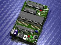
Atmega fusebit doctor, as name says it, device for repairing dead Atmega family AVRs by writing wrong fusebits. Most common mistakes or problems are a wrong clock source (CKSEL fusebits), disabled SPI programming (SPIEN fuse) or disabled reset pin (RSTDISBL fuse). This simple and cheap circuit will fix you uC in a fraction of a second. If in first case we can help ourself with clock generator, then in 2nd and 3rd cases bring uC back to life is impossible with standard serial programmer. Most of people do not decide to build parallel programmer because its inconvenient and its cheaper and faster to buy new uC.

This circuit uses the parallel high-voltage programming method. Atmega8(doctor) has saved in it’s memory signatures of most common AVR Atmega uC’s, just put your dead mega in socket, press the START button, and enjoy your good-as-new processor. There are three slots on board, for most common AVR’s, pins compatible with: Atmega8, Atmega16, Attiny2313. There is also an extra goldpin connector with all signals so you can attach your own adapters for other types of processors, in trough-hole or surface-mounted, you can use the breadboard for this – just connect signals to correct pins. How? Check your AVR datasheet, go to “memory programming” and then “parallel programming” – check the signal names, all signals are described under the DIP40 slot. In doctor memory there is a lot of free space so project may be developed all the time. One sided PCB with 55mm x 92mm dimensions. On top side you need to solder several jumpers, or, make this PCB as double sided – choose yourself. Power: stabilized 12V. Resistors from R7 to R23 may be in 100ohm to 10K, but i suggest from 470ohm to 1K. You can find extra RS232 output, connecting to this (at 38400 bps) we will receive all information about fixing process – see exemplary printscreen in gallery. Of course terminal is not needed, all we want to know we get from leds.

ATTENTION! While mounting the DIP40 slot, you must to remove it pins from 29 to 37. These pins must not have electrical contact with inserted uC pins. Take a look at this pic, these you must remove from slot:


Firmware 2.04:
-fixed couple of bugs
-added new processors support, total 106 (138)
-internal clock change to 1MHz, budrate on UART output change to 2400bps

ATTENTION, FUSEBITS! If you make an update of firmware to 2.04, please change the internal clock generator to 1MHz. If you make this circuit from beginning, just set the EESAVE fusebit – 1MHz clock is already set as default.

Full list below:
1kB:
AT90s1200, Attiny11, Attiny12, Attiny13/A, Attiny15
2kB:
Attiny2313/A, Attiny24/A, Attiny26, Attiny261/A, Attiny28, AT90s2333, Attiny22, Attiny25, AT90s2313, AT90s2323, AT90s2343
4kB:
Atmega48, Atmega48P/A, Attiny461/A, Attiny43U, Attiny4313, Attiny44/A, Attiny48, AT90s4433, AT90s4414, AT90s4434, Attiny45
8kB:
Atmega8515, Atmega8535, Atmega8, Atmega88, Atmega88P/A, AT90pwm1, AT90pwm2, AT90pwm2B, AT90pwm3, AT90pwm3B, AT90pwm81, AT90usb82, Attiny861/A, Attiny87, Attiny88, Attiny85, AT90s8515, AT90s8535
16kB:
Atmega16/A, Atmega16U2, Atmega16U4, Atmega16M1, Atmega161, Atmega162, Atmega163, Atmega164, Atmega164P/A, Atmega165/P/A/PA, Atmega168, Atmega168P/A, Atmega169/P/A/PA, Attiny167, AT90pwm216, AT90pwm316, AT90usb162
32kB:
Atmega32/A, Atmega32C1, Atmega323/A, Atmega32U2, Atmega32U4, Atmega32U6, Atmega32M1, Atmega324, Atmega324P/A, Atmega325, Atmega3250, Atmega325P, Atmega3250P, Atmega328, Atmega328P, Atmega329, Atmega3290, Atmega329P, Atmega3290P, AT90can32
64kB:
Atmega64/A, Atmega64C1, Atmega64M1, Atmega649, Atmega6490, Atmega640, Atmega644, Atmega644P/A, Atmega645, Atmega6450, AT90usb646, AT90usb647, AT90can64
128kB:
Atmega103, Atmega128/A, Atmega1280, Atmega1281, Atmega1284, Atmega1284P, AT90usb1286, AT90usb1287, AT90can128
256kB:
Atmega2560, Atmega2561

106 total supported processors
Slash character with the “P/A/PA” means that the processor in newer versions/revisions still has the same signature and fuses, for example record “Atmega165/P/A/PA” includes following processors: Atmega165, Atmega165P, Atmega165PA. If we count those processors separately, we have total 138 processors.

Regards
Fragrance

Demo Video

Atmega HVPP fusebit doctor.mp4 - 4shared.com - partage et stockage de fichiers en ligne - télécharger
 

REVIVE AN ATMEGA32:

SIMPLE AND POWERFUL

I was able to revive a Atmega32 by replacing the 16mhz xtal for a 12mhz xtal then reprogramming to defaults.
 

Fragrance said:
here is what you need
that seems like a lot of trouble just to reprogram the fuses. Most people cannot make a 2 sided board at home.
By the time you factor in all your parts, the board, all the adapters
it is easier [and cheaper] to just buy one already built!

I have one of these:
**broken link removed**

works like a charm. All of the sockets are on one board, no need for multiple adapters.
I guess if you want to build one yourself, the fuse doctor would be the way to go.
 

This method works for me: when I need an external clock to erase / burn / reprogram fuses of AVR where it's fuse have been programmed so the AVR works only with external crystal, I just place the AVR on a breadboard, connect ISP cable to it and use one crystal (4/8 MHz) with two 22 pF caps just at the Xtal1 and Xtal2 PIN of the AVR itself. This way the AVR works well with ISP programmer.
 

Erasing the ATMEGA128RFA1

Just for information for anyone who screwed up the ATMEGA128RFA1 fuses. The 1MHz clock signal must be applied to CLKI (pin 33) and *not* XTAL1 like the other devices.

cytan
 

Get a Dragon from Digikey for $50 and set up the Parallel zif socket - it will unlock any atmel that will fit in it
 

I faced a similar problem like this...But mine was stupid..I accidentally configured the fuse bits to use its internal 1 Mhz clock..And thus was unable to reprogram the mega16..but after closing the "slow sck" pins of the usbasp which by the way uses atmega8 with a jumper enabled me to access the chip once again..I guess the greater frequency of the usbasp was obstructing it from accessing..after that i reprogrammed the fuse bits to use its external 16 Mhz oscillator..
 

I accidentally configured the fuse bits to use its internal 1 Mhz clock..And thus was unable to reprogram the mega16
usually the problem is accidentally programming the fuses for an external clock. when there is no crystal or oscillator connected, the device cannot be accessed.

The 1 MHz internal oscillator is too slow for usbasp, unless the jumper is installed. Newer versions of usbasp code do not need the jumper. If an updated avrdude.exe is used, you can control the sck frequency right from the command line. An example command line:
Code:
avrdude -c usbasp -p t45 -C avrdude.conf [B][U]-B 250 [/U][/B]-e -U flash:w:hexfile.hex
pause


These are some new commands i guess...By the way how can these commands control the sck frequency without reprogramming the atmega8 of USBasp or closing the slow sck pins..really nice upgrade..
 

ctownsend,
worked like a charm. Was able to recover my atmega328p using your instructions. I just set the CLKOUT fuse on the attiny2313 and connected it to the clk in pin on the atmega328p. I was unable to read the device, but could erase it via ISP, and then it could be read normally. I know this thread is 7 years old, but just wanted to say thanks... for anyone else having trouble that does not want to build/buy another cable or programmer; check page one, ctownsend has it right.
 
Last edited:

Status
Not open for further replies.

Similar threads

Part and Inventory Search

Welcome to EDABoard.com

Sponsor

Back
Top