Continue to Site

Welcome to EDAboard.com

Welcome to our site! EDAboard.com is an international Electronics Discussion Forum focused on EDA software, circuits, schematics, books, theory, papers, asic, pld, 8051, DSP, Network, RF, Analog Design, PCB, Service Manuals... and a whole lot more! To participate you need to register. Registration is free. Click here to register now.

Equation for a Class D amplifier Inductor Power Dissipation

Status
Not open for further replies.

AJAB

Junior Member level 1
Joined
Oct 15, 2013
Messages
18
Helped
0
Reputation
0
Reaction score
0
Trophy points
1
Activity points
123
Hi,

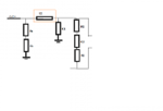
I am trying to get an equation for calculating the power dissipated by Class D amplifier in output circuit in the inductor of LC filter.
I am confused as I am getting different equations on different websites.
Snapshot.png
What is the difference between DC power and AC power dissipated.
DC power = V/2*freq*L
AC power = V/|XL|

is this correct?

Thanks,
Archana.
 

Neither are. The power dissipated in the inductor is the RMS current times the inductor resistance.
 

.. RMS current through inductor is V/|XL|...rt.... ( I did a mistake in previous post...I said this is power)
So PD = square of (V/|XL|) * DC resistance of Inductor...


Am I correct???

And what role does the resistor R1 play for considering Power Dissipation?
 

R1 is part of XL which determines the current through the inductor. Note that the inductor current becomes larger if an additional load is attached.
 

R1 is part of XL which determines the current through the inductor. Note that the inductor current becomes larger if an additional load is attached.

So Irms = V/sqrt(square of (2*pi*F*L) + square of (R1))

and then Power Diss. = square of Irms * DC resistance of L

Correct? :)
 

You need to calculate the equivalent impedance of all the components together. You can't use the impedance value of the components individually.
 

So Irms = V/sqrt(square of (2*pi*F*L) + square of (R1))

and then Power Diss. = square of Irms * DC resistance of L

Correct? :)
No, that formula is wrong. A precise solution should account for the fact that inductor ESR is frequency dependent, and probably nonlinear as well. A good compromise is to decompose loss calculations into low and high frequency contributions, with each having its own inductor ESR.
 

Sorry! This may be very basic, but I am not sure I understood this. :-?
Can you please tell me this in equation form..??
 

Giving exact equations would depend on the full circuit, including load and source, which you don't show.
 

Hi,

This is the circuit.

Help me!

I modified the circuit...So this is same as the ckt I posted originally. These are the components which I think will affect inductor current.
 

Attachments

  • asset.png
    asset.png
    6.5 KB · Views: 74
Last edited:

Well then it might be quite complicated if there's that many components... though I presume that most of those components don't significantly affect inductor current. Also that circuit only shows the source as a simple voltage, but in reality I presume its a PWM-driven full bridge, and the frequency and bus voltage of that source will define your high frequency losses.
 

In a reasonable design, the load current would be the dominant part of the total inductor current. In addition, there will be some core losses and potentially, skin effect losses might play a role.
 

Yes, this is a PWM driven full bridge.

But still In my circuit what are the components that affect inductor current?? :???:
 

But still In my circuit what are the components that affect inductor current?? :???:
All of the components shown in your first picture, as well as the stuff you didn't show because you didn't think it was important.

Your second picture is too small for me to make out any details - it just looks like seven resistors.
 

ok. this is the ckt. **broken link removed**

I have not shown a common mode choke here between C1 and C6 branches.
Please let me know your inputs.
 
Last edited:

If that's an 8 ohm speaker then it's current will likely dominate the current through the inductor, assuming the reactive components have a much higher impedance at audio frequencies. The high frequency current components from the switching frequency should be relatively small and would contribute little to the inductor power dissipation.

The easiest way to determine the inductor current is just to simulate the circuit with a Spice simulator.
 

ok. I will check.

- - - Updated - - -

If that's an 8 ohm speaker then it's current will likely dominate the current through the inductor, assuming the reactive components have a much higher impedance at audio frequencies. The high frequency current components from the switching frequency should be relatively small and would contribute little to the inductor power dissipation.

So why is this wrong : ���� =��/(2∗��∗��)..?? and PD = IL*IL*DC resistance???
 

Status
Not open for further replies.

Similar threads

Part and Inventory Search

Welcome to EDABoard.com

Sponsor

Back
Top