Continue to Site

Welcome to EDAboard.com

Welcome to our site! EDAboard.com is an international Electronics Discussion Forum focused on EDA software, circuits, schematics, books, theory, papers, asic, pld, 8051, DSP, Network, RF, Analog Design, PCB, Service Manuals... and a whole lot more! To participate you need to register. Registration is free. Click here to register now.

Equal perceived brightness with different LED colors?

Status
Not open for further replies.

Altazi

Newbie level 3
Joined
Sep 16, 2015
Messages
3
Helped
0
Reputation
0
Reaction score
0
Trophy points
1
Activity points
38
Hello All,

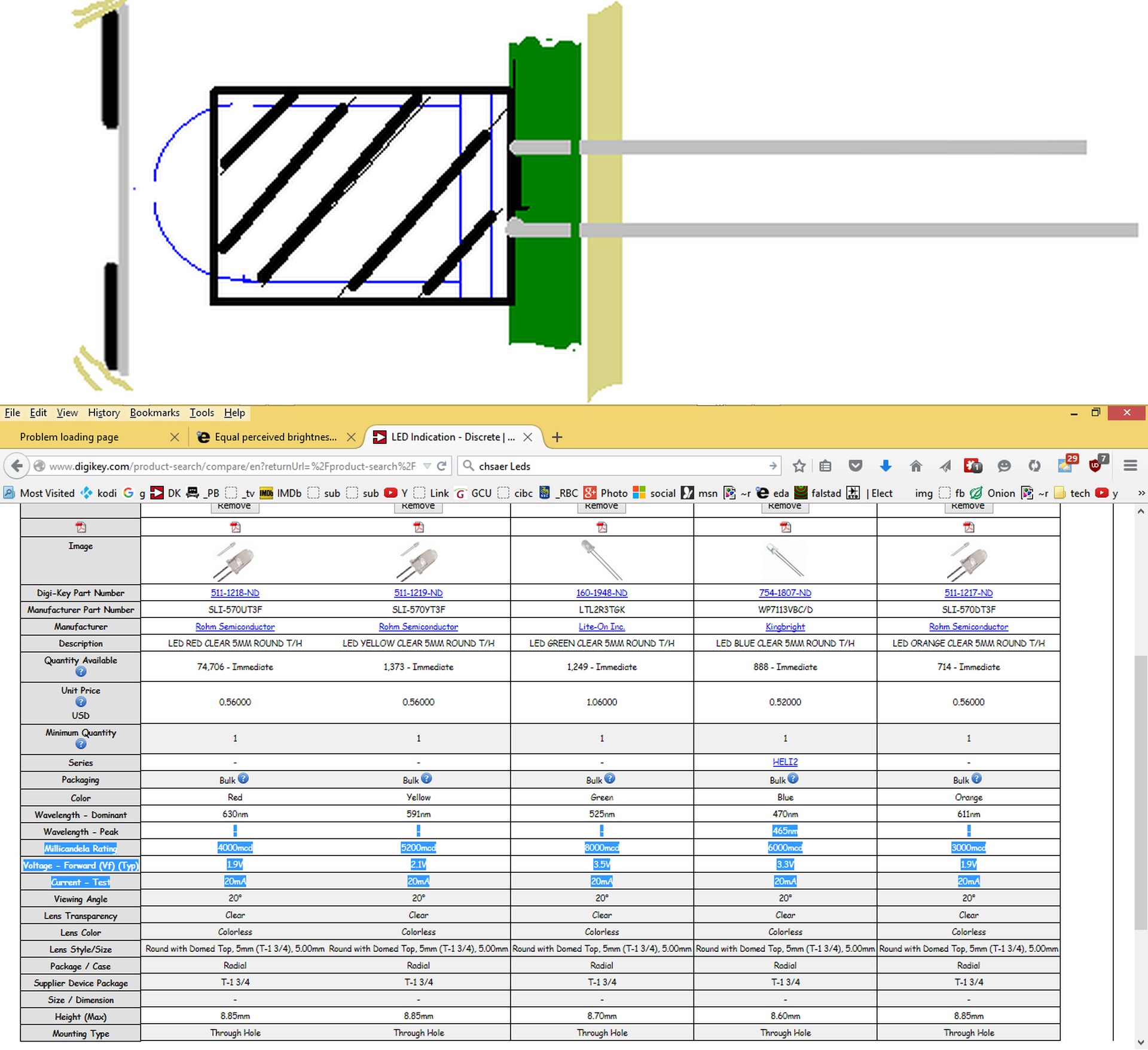
I am creating a front panel which uses discrete LED indicators – red, orange, yellow, green, and blue. Looking on Digi-Key (doesn’t everyone?) at the LEDs shows their luminous intensity in millicandelas (mcd), along with their dominant and peak wavelengths.

I would like all of the different colors of LEDs to appear to have the same perceived brightness, and haven’t had any success in searching for this. I know the human eye doesn’t respond equally to all wavelengths of light, so what do I do next? Would 100mcd LEDs in all colors appear to have the same brightness? Or should I normalize them based on the human eye response?

A separate, but related question: How bright is a 100mcd LED? Is it bright enough to be easily visible when located behind a polycarbonate overlay in muted sunlight? 400mcd? The mcd values are all over the map. I’d like the LEDs to be readily visble, but not painfully bright.

I would prefer to calculate the results rather than just buy a bunch of differently-rated LEDs and empirically determine what is equal brightness. Thanks in advance!
 

Final edit ;)

Yes mcd of any color is the same perceived intensity calibrated according to CIE eye weighting but acuity depends on contrast and blue is the weakest, yellow is strongest, so no it varies. http://www.workwithcolor.com/hsl-color-picker-01.htm

100 mcd is not very bright from a 5 mm LED diffused over say a 10mm diameter white film on a sunny day.

Go with 30 deg 5,000+ mcd and reduce current to suit brightness or 2000mcd if SMT close to PU diffuser.

If you want deep Red, 660nmD these are lower efficacy , GaAs so Iv won't be as high as AlInGaAs (HB) (615~630nmD)

I have a few boxes of Yellow, 10Cd @30deg and white 20Cd @ 30deg. @20mA which work really well at 2mA to 20mA from night to daytime.

When diffused there is beam spreading and transmission loss.

LCD's are backlit @ 250 lumen/m² which is adequate and not blinding in bright sun, so one would have to convert luminous Intensity, Iv to lumen/m² knowing the gap , beamwidth and transmission loss.

It all depends on the size of the aperture you choose, how you block adjacent LED scatter behind the panel etc on the beamwidth.

Can you define your mechanical design? (with respect to muted sunlight and panel aperture size, gap, SMT, THT etc. and glare, acuity needs.

- - - Updated - - -

Equal brightness will not be true for someone who is color blind.

Full daylight is 10,000 lumen or 10k lux/m²,
Direct sun is 100k lumen. Avoid this.
Muted sunlight may be 1000 lumen?
Moonlight ~ 1 lumen

If surface reflection is 10% from diffusion and absorption then 1k lumen it will be 100 lumen , so emission/sun reflection ratio expressed as SNR for 250 lumen/m²(LCD max ref) is 2.5= 250/100 so barely noticeable in 1k muted sun, but at night it will be glaring 2500 ratio. (in the ballpark)

If you want to prevent glare, use a photo diode to sense ambient light and adjust current. I wish they would do this for Stop lights which are glaring at night and just barely visible in twilight looking into the sunset.

If you mix RGB with equal intensity, you should get natural daylight white.
Here is an OLED with 96% CRI color accuracy. Notice how the Blue, Green Red spectrum intensity is well matched. ( within 15%)
OLED.jpg

This difference between Warm white and Cool white is 50% lower blue or 50% relative lower RG. Natural white, will be equal and around x,y of 0.37,0.37.

But acuity (perceived detection) and glare ( brightness ratio to ambient and size.) depend on the ambient light, reflection coefficient and distance among many other factors.
 

Thanks, SunnySkyguy,

The LEDs (type unspecified, could be SMT, could be T/H) will be located on a PCB mounted behind an aluminum panel with a thin polycarbonate graphic overlay over the front. The overlay will have small (0.10" - 0.20" diameter) translucent clear windows directly over the LEDs, so it's not a backlight situation. The distance between the overlay and the LED is TBD, but it is expected to be as small as possible, in the range 0.10" - 0.20". The LED emission cone angle is expected to be in the range 70-90 degrees. I can't seem to find many devices having luminous intensities in the 1000mcd+ range . . .
 

Go with a 4mm(0.16") D tapered hole use a soft shim on board for consistent heights and protect LED wire bond from solder shear forces.

Use diffused 5mm LED , since your polycarb is clear.

If LED leaks out adjacent aperture, consider heatshrink over LED to a few mm below tip or adjust for appearance.
led pcb.jpg

Consider a photo diode to control bias current. from 5mA night to 20mA day.
Consider these >= 1000mcd
https://www.digikey.com/product-sea...1&stock=1&quantity=0&ptm=0&fid=0&pageSize=500
 

Different color led's require different voltages to start them lighting up.

Furthermore you can expect the led's to require different amounts of current, so that our subjective eyes see the colors shine at the same intensity.

-----------------------------------

To check how the led's compare in brightness, as grayscale only...

A camera's response is roughly the same as our eyes. Photograph them with a digital camera (don't use the flash). Choose the grayscale effect, either in the camera, or in graphics editing software.
 

If you find the muted sunlight is pretty dark, get some samples and verify with diffused LEDs (tinted) and compare with HB clear diffused in your specified ambient light and test it for appearance. If bright enough , consider Kingsbright assembled mounted ~300mcd.

Intensity is fairly linear from 10% to 100% of test current, so you can gauge results to see what you need.

Good idea with camera.. Brad.

You can also use Panasonic CIE corrected 5mm photodiodes from 5V to give linear Lux levels. (cheap) The buffered load R determines the LUX at a given range. (=lumens)

I've used these for LED test equipment at 1m distance with 5V LDO to power a bunch of them at different angles and into a rotary switch to a cheap DMM.

https://www.digikey.com/product-detail/en/AMS302/255-2655-ND/2125641
 

Thank you, all. I know all about LED forward voltages and current requirements, but wasn't clear on how to set perceived equal brightness levels across different colors. There are some good ideas here. The one thing I don't have to worry about is viewing under dark conditions - this product is only going to be viewed during daylight hours.

I do believe I'm not going to look at any LEDs whose luminous intensity is below 300mcd. Unfortunately, it looks as if I am still going to have to get a bunch of LEDs and current limiting resistors to empirically determine the correct "recipe" for equal brightness. Darn, I was hoping to avoid that. I would rather spend an hour doing calculations than 10 minutes doing soldering.
 

my 10 minutes of Digikey search filtering

I used my big list of parts and incrementally reduced range of values to find a common range of values.
The result was 20deg for ROYGB > 3000mcd for BLue and <=8000mcd because of green
Thus Blue will require 20mA but Green may only need 6mA or so

Now choose from these then compute Rs to get If from 5V and Vf to normalize the intensity Iv
Always use eye corrected wavelengths Lambda D or dominant wavelength or WD for color reference
I reduced the thousands to 17 values for 5 colors
https://www.digikey.com/product-sea...1&stock=1&quantity=0&ptm=0&fid=0&pageSize=500
this took 10 minutes.
Normalize intensity to the lowest color Iv by reducing current with a larger Rs. Each LED will have ~ 15 Ohm ESR internal.

Note that dome height varies between colors by 0.25mm which may affect gap unless you use a custom shim for soldering.

To improve indicator appearance. I suggest wet-dry sandpaper and lightly sand dome middle surface to diffuse lens and make the 5mm glow rather than the 1.5mm chip inside, since these are all water clear and will have significant glare.

Also Yellow comes in two shades canary yellow 589nmD and amber yellow 595
HB RED is sometimes 615~630nmD and deep Red 660nmD is not avail in HB so 630nmD is best Red

If I used a spreadsheet to compute Rs and If for matched Iv I would consider Vth and Vf for each colour to get better accuracy. Vth is the forward thresold voltage at say 10% of If or 2mA then ESR*18mA+Vth=Vf nominal.

I might have selected the parts in less time it took to write how to do it. But I thought you would prefer this.

All LEDs I order from factory have ESD diodes, yours will not. So beware of ESD.

Also beware of handling precautions for lead bends, length and solder distance, time and temp. Many Process engineers have damaged/wounded LED's from ignoring these precautions causing early field failures.

I suggest 5mm away from base and 3 seconds max solder time at 360'C tip max since heat velocity is >1mm per second to gold wire bond along lead and thermal sheer forces may damage connection from excess solder time or too close to base. Longer leads on standoffs allows more time. This is from personal experience from client failure rates of 1~5% due to solder process errors. If soldering each lead sequentially without cooling time, I would always choose cathode(-) with chip wirebond 1st, which is more sensitive than Anode wirebond or use spacer standoffs to extend Solder time and normalize dome tip gap to case.

- - - Updated - - -

7397816200_1442521088.jpg


You can choose Rs values from Iv and Vf above.

  • my preference for colours. (nmD) are above
  • Diffused lens is preferred and easily created.
  • heatshink over LED is optional depending on your design to block adjacent LED light.
  • If pullup to a Node with 0Ω jumper to 5V, then you can dim all with another (shared) Rs with modest differences in balance
  • e.g. for a 1V drop to reduce intensity 40% of original est. 70mA (total) *40%= 28mA total or 1V/28mA = ~36 Ω (approx)
 

Status
Not open for further replies.

Part and Inventory Search

Welcome to EDABoard.com

Sponsor

Back
Top