Continue to Site

Welcome to EDAboard.com

Welcome to our site! EDAboard.com is an international Electronics Discussion Forum focused on EDA software, circuits, schematics, books, theory, papers, asic, pld, 8051, DSP, Network, RF, Analog Design, PCB, Service Manuals... and a whole lot more! To participate you need to register. Registration is free. Click here to register now.

Energy Meter using PIC

Status
Not open for further replies.

dikshac

Newbie level 1
Joined
Sep 19, 2013
Messages
0
Helped
0
Reputation
0
Reaction score
0
Trophy points
0
Activity points
57
I am working on a project where I am going to build a watt-hour meter. Currently, I am working on measuring voltage. I was planning on using PIC Microcontroller.

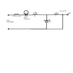
Say, I want to measure voltage across a 8Watt DC Bulb/LED which operates at 12-18VDC. I am going to scale this voltage drop between 0-5V and then send it to ADC on my microcontroller. Here's the circuit that I have designed.

design-voltmeter.png

Explanation : I want to limit Va to 5V (Scaled Voltage going to ADC on MCU). Using voltage divider rule -> Va/Vin = R1/(R1+R2) => 5V/18V = R1/(R1+R2) => R2=2.6*R1
I decided to choose R1 as 1.3kOhm and R2= 3.38kOhm.
I am also using a 5.1V zener diode to protect my MCU by limiting current going to ADC to 5V.

I just want to check with you guys if this would be ok. I know there's something wrong with the circuit. I don't think this circuit will really send the voltage drop across the load (bulb/LED) to ADC. I am not sure where to place my load.
Can you help me figure out what exactly I should change in the circuit? I have done my research and I'm struggling at this point.

I have just started this project and I don't have any prior experience with MCU or Designing... I have been reading a lot and designed this based on what I picked up. :lol:

Any help/suggestions would be appreciated.
 

Attachments

  • design-voltmeter.png
    design-voltmeter.png
    38 KB · Views: 101

To start off, I will try to just give you some pointer/ideas -
you want to measure the voltage drop across the lamp/bulb, so you must have circuit sense lines connected on either side of the bulb.
you do not want your measuring circuit to greatly influence/change the reading of the voltage of the bulb, or the current going through it -> this means you want a very high resistance/impedance looking at the sense lines.
you then want to convert a 0 - 18V signal into a 0-5V signal for your ADC (or 0 - 3.3V if your ADC runs on that).

There are multiple ways to do this. One of the more straightforward methods would use a device called an operational amplifier (op-amp). It has (2) high input impedance inputs for measuring voltage differences. With the appropriate choice of feedback components between its output and its input, it could make a linear transformation of 0-18V -> 0-5V.

This has given you several things to look into for designing a circuit that can do what you wish.
 
Kripton2035, wouldn't that be sending the voltage drop across 3.3K resistor to ADC?

Correct me if I am wrong.

- - - Updated - - -

ftsolutions - Do you have a reference circuit to support what you're saying about using an op-amp... that would help me understand better.

Thanks guys! :)
 

What do you plan to have for power supply voltages in your design? This would impact an op-amp based design.

If you want to go with a very simple circuit such as the voltage dividers which Kripton2035 shown, and can accept that the ground reference for the bulb/load is to be the same as for your other circuitry, then you can do it that way also for lower cost - though you may want to increase the resistor values (keep same ratio) so that you are affecting the measurement less. (ex. try 100k and 33K resistors, or other resistor combinations shown in each line of Kripton's suggestions). The simple voltage divider is just performing the same linear scale conversion of 20V -> 5V as mentioned (20v * 3300/13300 = 4.96V... it is good to leave some extra "headroom" in the maximum range of any measurment circuit ). This resistor circuit is in parallel with the bulb and so there is up to 1.5mA (at 20V) going through the measurement circuit, which might impact your current measurement - though we haven't even talked about that yet. If you make these resistors 10x the example value, it will reduce the current by 10x, which wouldn't be a bad thing. Generally, you want the measurement circuit to have as tiny an effect on the things being measured as possible.

If this is for a homework or class assignment, we do not want to be handing out answers if you do not have basic understanding of voltage and current dividers and basic circuit analysis. You will not learn the necessary skills otherwise.
 
Guys, thanks for your help and patience.

ftsolutions - This is not a homework assignment... and I am familiar with basics of circuits - current and voltage divider circuits.

The two resistors being parallel to the bulb, the voltage drop across the two branches would be the same. And the total voltage in the second branch is being divided between the two resistors (not equally divided though approximately a third)

I understand the circuit and the voltage division inorder to limit the voltage to ADC to 5V. However,
The only thing I am confused about right now is if I wire up my circuit the way Kripton has it there wouldn't I be sending the voltage drop across 3.3k resistor to ADC. How does that help me? What does that tell me about the voltage drop at the load/bulb? What if I have a variable power supply (12V-18VDC)?
 

It seems you are looking to measure the watt-hour consumed by the bulb which has a non-linear resistance.
 

@KerimF - I really haven't decided on the load yet. I could really use any load I want. I am just trying to pick up on some concepts as of now... Once I get this right, I can go ahead and design the circuit for the load of my choice. I'd eventually like to choose a load with linear resistance.
Do you have any ideas on my last question? Which voltage are we actually sending to ADC... Looking at Kripton's circuit the voltage that we are sending to the MCU is going to be the Voltage Drop across the 3.3k resistor.
 

So if the measured voltage across the 3.3K is V_adc:
V_bulb = V_adc * ( 10 + 3.3 ) / 3.3
V_bulb = V_adc * 4.03
I think the MCU can do this simple multiplication.

In my products, since I can't get MCUs with ADC function, I convert a voltage to time by resetting a capacitor and measuring the time that the voltage (thru a resistor) needs to charge it up to a reference voltage. Usually the rate of charge is not linear (exponential). So I add a data table in the MCU to give me the voltage in function of time.

Since you have an ADC pin on your MCU, your measurement is much easier ;)

Added:
I asked you about the load type because measuring the watt-hour for DC voltage/current is easier than AC. I guess you know why.

Added:
Perhaps someday, you will be interested to build an Amp-hour meter that could be useful to monitor the charging/discharging of big rechargeable batteries. You will just need amplifying the voltage on the shunt of an amper meter (connected in series with a battery terminal) which is usually in mV.
 
Last edited:
Ok, that was my question. So, that is taken care of by programming. That's exactly what I was looking for.
Thanks, Kerim! :)
 

Status
Not open for further replies.

Part and Inventory Search

Welcome to EDABoard.com

Sponsor

Back
Top