dikshac
Newbie level 1

- Joined
- Sep 19, 2013
- Messages
- 0
- Helped
- 0
- Reputation
- 0
- Reaction score
- 0
- Trophy points
- 0
- Activity points
- 57
I am working on a project where I am going to build a watt-hour meter. Currently, I am working on measuring voltage. I was planning on using PIC Microcontroller.
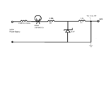
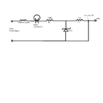
Say, I want to measure voltage across a 8Watt DC Bulb/LED which operates at 12-18VDC. I am going to scale this voltage drop between 0-5V and then send it to ADC on my microcontroller. Here's the circuit that I have designed.

Explanation : I want to limit Va to 5V (Scaled Voltage going to ADC on MCU). Using voltage divider rule -> Va/Vin = R1/(R1+R2) => 5V/18V = R1/(R1+R2) => R2=2.6*R1
I decided to choose R1 as 1.3kOhm and R2= 3.38kOhm.
I am also using a 5.1V zener diode to protect my MCU by limiting current going to ADC to 5V.
I just want to check with you guys if this would be ok. I know there's something wrong with the circuit. I don't think this circuit will really send the voltage drop across the load (bulb/LED) to ADC. I am not sure where to place my load.
Can you help me figure out what exactly I should change in the circuit? I have done my research and I'm struggling at this point.
I have just started this project and I don't have any prior experience with MCU or Designing... I have been reading a lot and designed this based on what I picked up. :lol:
Any help/suggestions would be appreciated.
Say, I want to measure voltage across a 8Watt DC Bulb/LED which operates at 12-18VDC. I am going to scale this voltage drop between 0-5V and then send it to ADC on my microcontroller. Here's the circuit that I have designed.

Explanation : I want to limit Va to 5V (Scaled Voltage going to ADC on MCU). Using voltage divider rule -> Va/Vin = R1/(R1+R2) => 5V/18V = R1/(R1+R2) => R2=2.6*R1
I decided to choose R1 as 1.3kOhm and R2= 3.38kOhm.
I am also using a 5.1V zener diode to protect my MCU by limiting current going to ADC to 5V.
I just want to check with you guys if this would be ok. I know there's something wrong with the circuit. I don't think this circuit will really send the voltage drop across the load (bulb/LED) to ADC. I am not sure where to place my load.
Can you help me figure out what exactly I should change in the circuit? I have done my research and I'm struggling at this point.
I have just started this project and I don't have any prior experience with MCU or Designing... I have been reading a lot and designed this based on what I picked up. :lol:
Any help/suggestions would be appreciated.


