geozog86
Member level 3
Hello!
I am trying to create a "ON OFF" button for my circuit, so that i can shut it down and i don't consume any power.
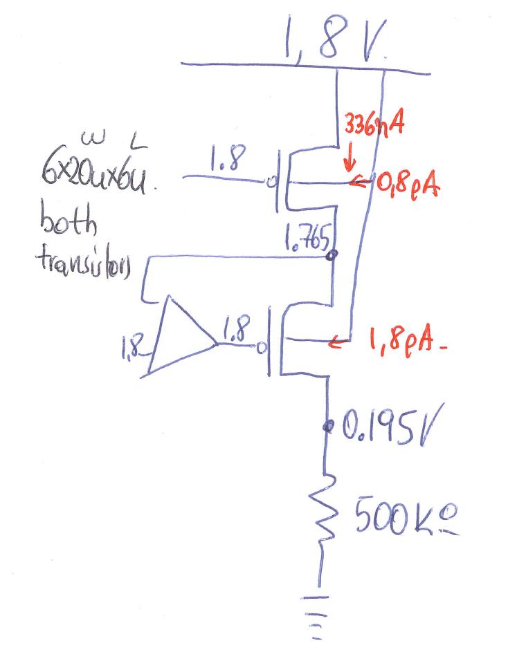
The problem is that this part of the design for example, thx to shutting down the biasing, i get A at VDD, and C (due to no current in the small amplifier) also at VDD. But B remains like 20mV below VDD, and the top transistor, even though having Vgs=0, conducts approx half a uA!!! I tried adding a small transistor (pmos with drain on B) but still that small current remains. I tried an nmos (drain on D) But still i have that small current.
Is there any way i can shut it down completely? Or it's an order of magnitude of current that i have to survive with?
(tota budget of current 100uA, this branch 1uA in normal operation, 0.5uA in "OFF"!!)
thx
I am trying to create a "ON OFF" button for my circuit, so that i can shut it down and i don't consume any power.
The problem is that this part of the design for example, thx to shutting down the biasing, i get A at VDD, and C (due to no current in the small amplifier) also at VDD. But B remains like 20mV below VDD, and the top transistor, even though having Vgs=0, conducts approx half a uA!!! I tried adding a small transistor (pmos with drain on B) but still that small current remains. I tried an nmos (drain on D) But still i have that small current.
Is there any way i can shut it down completely? Or it's an order of magnitude of current that i have to survive with?
(tota budget of current 100uA, this branch 1uA in normal operation, 0.5uA in "OFF"!!)
thx
")