Continue to Site

Welcome to EDAboard.com

Welcome to our site! EDAboard.com is an international Electronics Discussion Forum focused on EDA software, circuits, schematics, books, theory, papers, asic, pld, 8051, DSP, Network, RF, Analog Design, PCB, Service Manuals... and a whole lot more! To participate you need to register. Registration is free. Click here to register now.

ELISA PLATE READER

Status
Not open for further replies.

sadhucharan

Newbie
Newbie level 3
Joined
Nov 12, 2021
Messages
3
Helped
0
Reputation
0
Reaction score
0
Trophy points
1
Activity points
40
I am making an Elisa plate reader. Where i am using 450nm wave length LED, one Collimating Lens having 8mm focal length, one color sensor(TCS3472) and stm32f103c8 MCU.

The arrangement (bottom to top)is first LED will be placed then LENS will be placed over LED.96 well micro plate containing sample will be placed above 8mm of lens. Then color sensor will be above sample to read the light intensity passing through the sample.

Objective: the Absorbance(Abs) should change according to the predefined optical density(OD) of the solution.

PROBLEM STATEMENT: With reference to a well functioning reading machine My Abs. Value is not matching exactly. I am expecting the Abs. value should nearly parallel to the reference machine value or match with the exact value will be acceptable.

Thanks.
 

Not exactly means an error of 0.01% or 1% or 30%?

Klaus
The error percentage is not constant at each point. If the constant error will come i can make it correct. If i draw a graph between these two values,at middle point of graph the min error is like 3%.
Ref.Machine value(Abs.) My readings
0.6-------------------------->0.8
1.6-------------------------->1.65
2.739---------------------->2.02
 

Hi,

I don't know how this is meant to work.


Just from my little knowledge about optics:
When you place the lens in 8mm distance to the sample..
* you get a very narrow point of light at the sample (is this what you want)
(A narrow spot may increase error caused by unequal absorbance)
* the glass with it's thickness will diffract non centererd beams
* the sensor area is rather small, just 400x370um... maybe it just gets a very small signal so that you get a bad signal to noise ratio. Maybe a secind lens could improve on this ... or less distance, or increased LED brightness.

I recommend to find out the real reason for the problem. Do some tests:
* do a couple of tests without moving anything. This tells you the precision of the sysrem at all (repeatability). If there is a big difference in the results, then it's likely a "signal to noise" problem.
* If the results are rather stable, then do a coupke of tests but move the probe a little each time. This tells wheter the probe is equal over the area.
If the results are unstable, then you need to get a bigger area of light in the probe or a lens between probe and sensor.

Klaus
you get a very narrow point of light at the sample (is this what you want)- yes, narrow point is required bcz wide spot will disturb adjacent well of 96well plate.

the glass with it's thickness will diffract non centererd beams--yes,it is happening.
i am doing testing by changing the distance of lens and led brightness also.

i am not using any probe.
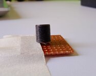
below lens is mounted over led, that will be placed inside the reader.there is a gap of 8mm focal length from lens to plate surface.color sensor is mounted above the plate.

please share some idea.

Thanks for giving your precious time.
 

Attachments

  • reader.jpeg
    reader.jpeg
    56.7 KB · Views: 127
  • lens.jpeg
    lens.jpeg
    57.7 KB · Views: 137

What's the unit of your reported measurements? Absorbance expressed as decadic logarithm, e.g. 2.0 corresponds to intensity of 0.01? How about spectral sensitivity of the reference detector?

However, if you have calibration solutions, there should no problem to make a calibration curve for your detector.
 

Status
Not open for further replies.

Similar threads

Part and Inventory Search

Welcome to EDABoard.com

Sponsor

Back
Top