Continue to Site

Welcome to EDAboard.com

Welcome to our site! EDAboard.com is an international Electronics Discussion Forum focused on EDA software, circuits, schematics, books, theory, papers, asic, pld, 8051, DSP, Network, RF, Analog Design, PCB, Service Manuals... and a whole lot more! To participate you need to register. Registration is free. Click here to register now.

Electronic latching swith using 555 problems

Status
Not open for further replies.

hafrse

Full Member level 3
Joined
Aug 6, 2007
Messages
169
Helped
1
Reputation
2
Reaction score
3
Trophy points
1,298
Activity points
2,413
Hello,

I have built an electronic latching switch with 555 based on a circuit diagram I found on the net. the circuit is not connected to a relay now , when I push and release the button, the output goes high at pin 3 as excpected , but when I pusg aging, the output at pin 3 goes low (0V) after a number of attempts. So, on is no problem but off it needs multiple attempts to get pin3 low.
Any clue what that could be?

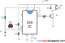
R1,R2,R3-1k Ohms Resistor
R4-100 Ohms Resistor
D1-1N4007 Diode
C1-1uf Capacitor
C2-10n Capacitor

Thanks
 

Attachments

  • latching relay using 555 ic (2).png
    latching relay using 555 ic (2).png
    18.9 KB · Views: 270
Last edited:

This circuit doesn't make a lot of sense to me. Look at the internal circuitry of the 555.

When you first power on, the cap will be at zero volts. When you close the switch it will force the output high, which in turn will charge the cap and turn the transistor on. That's it.

The voltage at pin 2 needs to be less than the voltage provided by the 555's internal divider. There's no way to discharge the cap. I have no idea why pushing the switch would EVER force the output low.

UPDATE:
What an awful, awful schematic. Apparently, pins 6 and 2 are supposed to be connected. Do you have that connection?
 

    hafrse

    Points: 2
    Helpful Answer Positive Rating
The circuit works only if you remove your finger from the button fast enough.
Try increasing the value of the capacitor C1 so that it charges and discharges slower.
 

    hafrse

    Points: 2
    Helpful Answer Positive Rating
6 and 2 are connected.
 

The circuit works only if you remove your finger from the button fast enough.
The circuit idea is that the static output voltage of R1 to R2||R3 voltage divider doesn't reach the threshold voltage of inputs 2 and 6 and the button can be pressed infinitely. The problem is however that with the present R1*C1 time constant of 10 µs the capacitor already charges during contact bounce. Increasing both R1 and C1 should avoid this situation. R1 should be larger than R2 and R3 to keep sufficient margin to input thresholds, particularly when using a CMOS 555.
--- Updated ---

6 and 2 are connected.
It would be good idea to follow standard schematic drawing rules.
 
The circuit idea is that the static output voltage of R1 to R2||R3 voltage divider doesn't reach the threshold voltage of inputs 2 and 6 and the button can be pressed infinitely. The problem is however that with the present R1*C1 time constant of 10 µs the capacitor already charges during contact bounce. Increasing both R1 and C1 should avoid this situation. R1 should be larger than R2 and R3 to keep sufficient margin to input thresholds, particularly when using a CMOS 555.
--- Updated ---


It would be good idea to follow standard schematic drawing rules.
Thanks , I will increase the value now ...
 

Here is a solution, using ATTINY85, that includes debouncing button.

1640179589121.png


mBlock 5.3.5 takes your block configuration (right window) and generates Arduino/AVR code for it.

iu


Use a Nano or UNO board to program chip. Note chip has A/D so one could
use that to turn off something if it got too hot, or too close, or other conditions.

You need external MOSFET to drive relay, unless its super low current turn on,
a couple of R's, and 1 Cap to bypass the ATTINY85 supply pin. Note could be
battery operated by putting ATTINY85 to sleep between button pushes. But
if relay on it would still draw current unless a mechanical latching relay. Also
needed is a regulator for ATTINY85, which could also be a zener with a R to create
shunt regulator. And a diode across relay coil to suppress turn off transient.


Regards, Dana.
 
Last edited:

    hafrse

    Points: 2
    Helpful Answer Positive Rating
hanks , I will increase the value now ...

The circuit idea is that the static output voltage of R1 to R2||R3 voltage divider doesn't reach the threshold voltage of inputs 2 and 6 and the button can be pressed infinitely. The problem is however that with the present R1*C1 time constant of 10 µs the capacitor already charges during contact bounce. Increasing both R1 and C1 should avoid this situation. R1 should be larger than R2 and R3 to keep sufficient margin to input thresholds, particularly when using a CMOS 555.
--- Updated ---


It would be good idea to follow standard schematic drawing rules.
Hello, R1 is changed to 22K, same problem, C1 changed to 10 uf same problem, I even replaced the 555 same problem . The problem is only on the "off" state . For some reason, when I replaced the values of the C1 R1, it became alsmost impossible to move to low state by pressing the button. The push button is a simple one, when preseeed, it stays closed until I release it.
 
Last edited:

Changing R1 to a higher resistance. With your 12V supply, the 555's internal threshold voltages are near 4V and 8V.

When the output is high then it and the capacitor will be about 10.6V. Then the button is pushed and it applies its 10.6V to pin 6 and is higher than the 8V threshold voltage so it resets the 555 causing the output to go low.
If the button is still being pushed then the capacitor voltage quickly drops almost to the 6V of R2 and R3. When the button is released then the capacitor voltage goes low which passes the 4V threshold voltage of pin 2 and the 555 is set causing the output to go high when it should not be set.
Hello,
R1,R2,R3 is 1K, C1 is 1uf as adviced by the auther of the circuit on the site I found this circuit diagram. I started to change the C1 to 10uf, it did not help, I changed R1 to 22k, it did not helped. I will measure the voltages as adviced
--- Updated ---

Changing R1 to a higher resistance. With your 12V supply, the 555's internal threshold voltages are near 4V and 8V.

When the output is high then it and the capacitor will be about 10.6V. Then the button is pushed and it applies its 10.6V to pin 6 and is higher than the 8V threshold voltage so it resets the 555 causing the output to go low.
If the button is still being pushed then the capacitor voltage quickly drops almost to the 6V of R2 and R3. When the button is released then the capacitor voltage goes low which passes the 4V threshold voltage of pin 2 and the 555 is set causing the output to go high when it should not be set.

How does the internal threshold voltages are set ( 4V and 8V)? and if I should try to increase C1 , what vaule should I use ? thanks

One more weired thing, when I tried to measure on the board, if I touch the ground with a wire, it seems to set the 555 to go low! so , if I press the push button , it goes high, and if I touch the ground with a wire, the 555 goes low (most of the attempts but not all) .
 
Last edited:

Besides debouncing the button, and glitch free power up, it would
be easy to add brownout detection to turn off the load, and further
on power loss save state of relay in ATTINY85 internal EEPROM so
upon power return relay could be put in its prior state.

Circuit would look something like this -

1640192408884.png


Keep this in mind for future projects.

Note SSR used in this example rather than conventional relay.


Regards, Dana.
 
Last edited:

The datasheet for the 555 explains how it works and even shows a voltage divider in it producing threshold voltages that are 1/3rd and 2/3rds of the supply voltage.
The original circuit is garbage and might not have been tested by the author.
 

Here is added coding that handles brownout condition handling -

1640198526515.png


Regards, Dana.
 

    hafrse

    Points: 2
    Helpful Answer Positive Rating
Thanks, I will consider moving to ATTINY85, solution after I am totally stuck using the simple 555.
Just consider it for future work. If you are not a coder and a visual learner its an easy way to get started.
Kids starting in 6'th grade are using it in many schools in US to program robots. There are many variants,
once you learn one they are all pretty much the same.

And they generate Arduino code which you can look at, a form of C/C++.

More sophisticated block programmers make doing stuff, like a talking volt or ohm or whatever
meter almost trivial without having to master multiple languages. An example here -

https://www.edaboard.com/threads/gui-codeless-processor-design.397358/#post-1708529 end of thread

Here is example of very capable timer producing various pulse trains to control generic
kinds of events (many folks trying to do this with 555 cascaded timers and other logic) -

https://www.edaboard.com/threads/moved-pulse-sequence-generator-smart-timer.398291/

Some of the other block programmers, Ardublock, Snap4Arduino, Node-Red,
Flowcode.....most are free.

Here is Tuniot used to do wifi stuff -


Note these are Atmel AVR and ESP8266 and ESP32 type processor solutions. Not just ATTINY.

Attached is the mBlock solution for the relay problem. As an aside there is a bug in mBlock when you
open program all the comment blocks user entered are misaligned, and you have to drag them around
by their title bars at top to get all the comments looking decent that were attached to the blocks. FYI.


Regards, Dana.
 

Attachments

  • ATTINY85 Latching Relay.zip
    56.5 KB · Views: 113
Last edited:

The datasheet for the 555 explains how it works and even shows a voltage divider in it producing threshold voltages that are 1/3rd and 2/3rds of the supply voltage.
The original circuit is garbage and might not have been tested by the author.
I also found another version using +5V supply, there they have used R1=100K, R2,R3 = 10K, otherwise every thing else is the same https://www.electronics-lab.com/project/toggle-on-off-switch/ it is a complete project with Eagle PCB files and a video showing a prototype
 

Status
Not open for further replies.

Similar threads

Part and Inventory Search

Welcome to EDABoard.com

Sponsor

Back
Top