Continue to Site

Welcome to EDAboard.com

Welcome to our site! EDAboard.com is an international Electronics Discussion Forum focused on EDA software, circuits, schematics, books, theory, papers, asic, pld, 8051, DSP, Network, RF, Analog Design, PCB, Service Manuals... and a whole lot more! To participate you need to register. Registration is free. Click here to register now.

Electrolytic Capacitor as Detector or LF Noise Source

Status
Not open for further replies.

edaprojects

Newbie
Joined
Jul 19, 2021
Messages
4
Helped
0
Reputation
0
Reaction score
0
Trophy points
1
Activity points
33
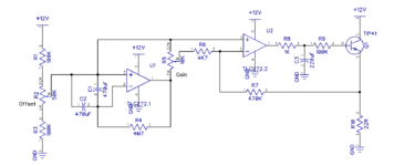
The attached circuit produces a sub audio frequency, non-repetitive complex waveform. It resembles noise processed through a low pass filter.

Can anyone please tell me what exactly is being detected? In other words, the likely environmental (or other) source of the "signal" detected by the two 470uF caps and being amplified.

Looking at the scope, there is no apparent power grid artifact.
 

Attachments

  • capactive_detector_amp.png
    capactive_detector_amp.png
    22.4 KB · Views: 153

Some electrolytics have internal chemical action going on which generates a tiny signal.
I have taken readings of an electrolytic connected to nothing except my meter. I was surprised to see the voltage rising and falling unpredictably in a small range. My DMM was set to the 200mV range. Input resistance is 1M Ohm.
 

So what can we attribute this to? Any way to isolate the cause?

I have used a variety of electro's in different settings. All exhibit the same type of behavior. I have found no way to influence it hands-off. But it does seem to change with capacitance value.

From my observations, I have the impression something external is being detected. Perhaps slight variations in atmospheric charge/pressure interacting with polarization of the dielectric. I am just guessing though.

It would be really interesting to find out for sure.
 

It's basically a noise generator, amplifying low frequency OP noise. Different capacitor values give different gain curves.

The circuit may be influenced by thermoelectric voltages and other enviromental effects, but it's not suited as speficic detector.
 
I assume you are referring to voltage or current op amp noise.

Any idea how the frequency spectrum of this would differ in character from reverse biased junction noise of a single transistor?

Narrower? Broader? "Tunable" with the cap? What I am thinking is that it might be an interesting alternative to explore.

Can you please identify what "other environmental effects" you refer to?
 

Are there any further comments or advice on using an electrolytic cap as a substitute for a reversed biased transistor? In particular with regard to the spectral "quality" of the noise.
 

Status
Not open for further replies.

Similar threads

Part and Inventory Search

Welcome to EDABoard.com

Sponsor

Back
Top