Continue to Site

Welcome to EDAboard.com

Welcome to our site! EDAboard.com is an international Electronics Discussion Forum focused on EDA software, circuits, schematics, books, theory, papers, asic, pld, 8051, DSP, Network, RF, Analog Design, PCB, Service Manuals... and a whole lot more! To participate you need to register. Registration is free. Click here to register now.

Electrical wire sizing

Status
Not open for further replies.

Joe_Kleyn

Newbie
Joined
Aug 15, 2022
Messages
3
Helped
0
Reputation
0
Reaction score
0
Trophy points
1
Activity points
52
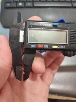
Hi all, I recently installed a 3700 kWp solar system with a 3500kWh inverter. I have some challenges with my efficiency and I was told that my current electrical wires might be too thin. Long story short, I bought some wires with a maximum rated capacity of 4600w and a thickness of 2.5mm2 described on the label. However, if a remove the insulation on the wire and I measure the actual copper thickness, it measures appr. 1.2mm thick. If I measure with the insulation, it is 2,5mm thick. My question is, how is home electrical wire thickness determined? With the insulation or without? It is maybe worth mentioning that I live in the Netherlands (Europe) TIA
 

Attachments

  • 20220815_121618.jpg
    20220815_121618.jpg
    351.6 KB · Views: 90
  • 20220815_121702.jpg
    20220815_121702.jpg
    276.2 KB · Views: 86
Last edited:

I measure the actual copper thickness, it measures appr. 1.2mm thick.
Is it solid or stranded copper. If stranded, how many wires? In any case it's never 2.5 mm², about 1.05 to 1.2 mm² depending on the stranding. Cross section specifications are always referring to conductor, not insulation.

Are you talking about the HV DC ("solar") cables or inverter grid connection? Would you mind to post a photo of the marking printed or engraved on the cable jacket?
 

Hi,

You mix a lot of things and miss to give important informations.

A pedantic view on your given informations:

Wire size depends on current (A) not on power (W). Wire size is never designed for Watts.
(You may calculate current from power, but for this you need to know Volts and in case of AC you additionally need to know power factor: I = P / (V * pf )

kWp means kilowatts peak (which is power)
kWh means kilowatthours (which is energy). An inverter is not designed for kWh at all.

Circular area is A = r * r * Pi, where r is the radius (half the diameter) and Pi is about 3.1416

The inverter has an input and an output. But carry different currents, thus need different wire sizes. You need to meantion which one you are talking about.
And in case of grid side cabling you need to tell whether it´s a 1 phase or 3 phase system.


Klaus
Apologies, I am not an electrician and I do not spesifically know which terms to use throughout. Yes i understand the formula and that the wire thickness is dependant on amperage.

Your post actually made me realize that I had to calculate the actual Area of the wire and compare on not just measuring the diameter. That solves my question.

However, the problem that I have is that the Voltage at the inverter keeps on increasing gradually untill it kicks into safe mode (253V) several times in a day resulting in significant drop in solar efficiency. I purchased a digital Volt meter that I can plug into a socket. There is a difference in Volts at my main db board vs at the db board at my inverter approximately 30m further. ( I know that there should be a V difference in order to supply the grid however, they do not increase at the same increments) When my inverter goes into safe mode at 253V, the V at my main db board is around 243V. I am trying to figure out if the Volt increase is coming from my grid or if it is a problem at my inverter. One of the comments was that the wires might be too thin hence my question.

Hi,

You mix a lot of things and miss to give important informations.

A pedantic view on your given informations:

Wire size depends on current (A) not on power (W). Wire size is never designed for Watts.
(You may calculate current from power, but for this you need to know Volts and in case of AC you additionally need to know power factor: I = P / (V * pf )

kWp means kilowatts peak (which is power)
kWh means kilowatthours (which is energy). An inverter is not designed for kWh at all.

Circular area is A = r * r * Pi, where r is the radius (half the diameter) and Pi is about 3.1416

The inverter has an input and an output. But carry different currents, thus need different wire sizes. You need to meantion which one you are talking about.
And in case of grid side cabling you need to tell whether it´s a 1 phase or 3 phase system.


Klaus
 

Apologies, I am not an electrician
No problems.

I had to calculate the actual Area of the wire and compare on not just measuring the diameter
correct

the Voltage at the inverter keeps on increasing gradually
again. You need to tell whether you talk about grid side or solar cell side voltage/current/power.

Also a sketch is always useful to explain things. then you can show where you did measureme the voltage, where the 30m cable is and so on.

I currently have no clear picture about your situation. This makes it impossible for me to give detailed assistance.

Klaus

The diameter for a wire depends on current. This means that a dedicated diameter can just carry a limited amount of current. This is because the current cuases dissipated power in the wire and thus the wire gets warm ... maybe even hot.

So for the heat of the wire it makes no difference whether your wire is 1m long or 100m long.
But for sure you have a dedicated voltage drop per meter (for a dedicated current).
So if your concern is "voltage drop" than this is a different story.
It has nothing to do with "current carrying capacity"

Klaus
 
Last edited:

No problems.


correct


again. You need to tell whether you talk about grid side or solar cell side voltage/current/power.

Also a sketch is always useful to explain things. then you can show where you did measureme the voltage, where the 30m cable is and so on.

I currently have no clear picture about your situation. This makes it impossible for me to give detailed assistance.

Klaus
Thank you, I will get all the information drawn up and reply on your post!
 

I initially din't see the photos in post #1.

Here's a specification of the H07V-U installation wire referred by the reel lable:

1660562994098.png


2.5 mm² wire has 1,78 mm copper conductor and 3,9 mm insulation diameter.

We should see a wiring sketch of the solar system to understand where the wire is used. Installation wire isn't dedicated to be used outside of enclosures or cable conduits, by the way.
 

You say that the diameter of the copper conductor you measured is 1.2mm. This will give a cross section of (pi/4)*1.2*1.2 or about 1.13 mm2. But the label on the roll says that the conductor cross section is 2.5mm2.

Something is not right.

If the wire is stranded (multiple round conductors), then the cross sectional area will be still less because there will be gaps between the conductors. You need to measure the diameter on one of the strands, calculate the cross section and multiply that with the number of strands in the conductor.

But the picture suggests that you have a solid conductor (single strand).

Inverter is like a transformer: it has one input side and one output side. Input power is approx equal to output power. Most modern inverters are very efficient and actual output power will be about 95% (or so) of the input power.

Output voltage will be around 220/240V and input voltage will be 12/24/36/48V (see the input label on the inverter).

The input wire size will depend both on the length and current. This wire is thick and hence expensive and hence you should try to place the inverter close the panel so that the copper loss will be less. If you are also having a battery setup, then the battery too should be close by.
 

Status
Not open for further replies.

Part and Inventory Search

Welcome to EDABoard.com

Sponsor

Back
Top