electronics_rama
Member level 3
Hello,
I'm not finding good resources to explain the effects of of common mode feedback block on the main amplifier. I have used the diode connected load in my CMFB circuit. So, the pole contributed by CMFB should be, gm/CL right? Am I correct here? Or how to check the pole contribution from CMFB by stand alone simulation in cadence?
- - - Updated - - -

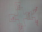
Please find the attached. I'm using one CMFB circuit to drive both the first stage and the second stage. Can I attain a unity gain frequency of 1GHz with this arrangement? Or should I use two separate CMFB circuits?
I have read in some papers that if one CMFB circuit is used, it will affect the unity gain bandwidth. Can anybody explain how it affects and how to go ahead here?
Thanks in Advance
I'm not finding good resources to explain the effects of of common mode feedback block on the main amplifier. I have used the diode connected load in my CMFB circuit. So, the pole contributed by CMFB should be, gm/CL right? Am I correct here? Or how to check the pole contribution from CMFB by stand alone simulation in cadence?
- - - Updated - - -

Please find the attached. I'm using one CMFB circuit to drive both the first stage and the second stage. Can I attain a unity gain frequency of 1GHz with this arrangement? Or should I use two separate CMFB circuits?
I have read in some papers that if one CMFB circuit is used, it will affect the unity gain bandwidth. Can anybody explain how it affects and how to go ahead here?
Thanks in Advance