Continue to Site

Welcome to EDAboard.com

Welcome to our site! EDAboard.com is an international Electronics Discussion Forum focused on EDA software, circuits, schematics, books, theory, papers, asic, pld, 8051, DSP, Network, RF, Analog Design, PCB, Service Manuals... and a whole lot more! To participate you need to register. Registration is free. Click here to register now.

Effect of series resistor at the gate of current mirror

Status
Not open for further replies.

jamesbond939

Newbie level 4
Joined
Dec 9, 2009
Messages
6
Helped
0
Reputation
0
Reaction score
0
Trophy points
1,281
Activity points
1,326
Hi all,

I notice for some current mirror implementation includes a series resistor that is connected to the gate of the diode-connected transistor of the current mirror.

7_1335633320.jpg


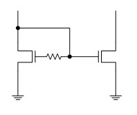
May I know the the purpose of the series resistor?

Thanks a lot.
 

hi, i've seen this circuit in a book talking about current-mode design longtime ago
if i'm right, the R here is to increase the bandwidth, the pole will change and it also add a zero.
you can calculate the small signal transfer func from the input current to the voltage of the M2 gate
 

A paper explains this design well
Search for :"A Novel High Speed Current Mirror Compensation Technique and Application" by T. Voo and C. Toumazou
 

By lagging the feedback FET, you will add peaking / sharpness
to the rest of the mirror rack. This can of course be overdone.
 

Status
Not open for further replies.

Similar threads

Part and Inventory Search

Welcome to EDABoard.com

Sponsor

Back
Top