Continue to Site

Welcome to EDAboard.com

Welcome to our site! EDAboard.com is an international Electronics Discussion Forum focused on EDA software, circuits, schematics, books, theory, papers, asic, pld, 8051, DSP, Network, RF, Analog Design, PCB, Service Manuals... and a whole lot more! To participate you need to register. Registration is free. Click here to register now.

[SOLVED] Editing of ASM file.

Status
Not open for further replies.

rn.ksheer

Newbie level 4
Joined
Jan 4, 2013
Messages
7
Helped
0
Reputation
0
Reaction score
0
Trophy points
1,281
Activity points
1,324
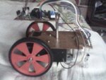
Hi. I have successfully completed constructing CERBERES robot given in https://webspace.webring.com/people/bt/tjaco/cerberes/cerberes.html . The robot works well but when it comes to a corner where both the sensors sense the object , The robot seems to get confused and gets stuck in the same place. The given code doesn't have any instruction for the motors, when both sensors are active. Will it be possible to add a instruction to make the robot turn 180 degrees, then start moving forward or to come backwards, turn left/right then start moving forward when both the sensors sense the object. I am very new to programming so i would require the help.

Sorry for my English :)
 

Attachments

  • V105.zip
    996 bytes · Views: 62
  • IMG_0057.JPG
    IMG_0057.JPG
    47.1 KB · Views: 67

Hi,

Well done for building the project :smile:

The code used is very old and quiet simple but if you want to learn pic Assembler then yes you can change it to do what you like.

As that site only gives the .asm file I assume to create the .hex file you already have Mplab and Assembler running on your PC.

What I would suggest you first do is not so much look at the actual assembler code, but the comments he has added to each line of code to explain his logic flow.

If you follow it though and create a flow chart for each step and build up a picture of how the whole routine / loop works, then I think you will see the point at which you can add your own code to overcome the problem of both sensors being active.

You can then add you own logic to the flow chart as to what you want it to do and see if it fits in ok.

Once you have done that come on back and we will try and help you create the assembly code needed to do it.
 

After looking into the instructions set for 16f84a, i found ANDWF or ANDLW operand can be used where we can compare the two inputs. If both the inputs are low (both the sensors sense the object) a sub routine can be called to perform a operation but i am not able to find detailed examples in Google.
 

After looking into the instructions set for 16f84a, i found ANDWF or ANDLW operand can be used where we can compare the two inputs. If both the inputs are low (both the sensors sense the object) a sub routine can be called to perform a operation but i am not able to find detailed examples in Google.

Hi,

I have added some comments to the code and perhaps you can follow it though and see the actual logic loop.

If you understand it ok, you will see that it cannot see both sensors at one time.

It looks for the left sensor first, if it is on it does a backleft, once complete it checks for the right sensor.

What may be happening is that the whole thing is running too fast, so if you change the main oscillator restistor R5 to 47k or 100k it will slow the logic down, but not the speed of the motors.
This may give you more time to see what is actually happening, I suspect it may be oscillating between both sensors at that corner so running on a bit slower it may behave ok.

If not you could add a little more delay time each time it backs off the object - see code.

When using a resistor and capactior R5 and C3 for the main oscillator exact timings are a little difficult to calculate, but I estimate the Delay routine is around 1/4 second - perhaps too fast.


Code:
;TJACO'S DESIGN GRAVEYARD: WWW.GEOCITIES.COM/TJACODESIGN		;
;22 JULY 2002								;
;CERBERES : MINI ROBOT WITH IR EYES  					;
;USES PIC16F84 µCONTROLLER						;
;WRITTEN IN MICROCHIP ASSEMBLY USE MPASM ASSEMBLER FROM MPLAB		;
;MPLAB CAN BE DOWNLOADED FROM WWW.MICROCHIP.COM				;

;***SET UP THE CONTANTS & VARIABLES****

       LIST            P=16F84
       ERRORLEVEL      -302    ;SUPPRESS BANK SELECTION MESSAGES

STATUS	EQU H'03'		;STATUS REGISTER
TRISB 	EQU H'86'		;TRISB REGISTER FOR SETUP OF PORTB
PORTB 	EQU H'06'		;PORTB REGISTER TO DRIVE PORT B
COUNT1 	EQU H'0C'		;COUNT VARIABLE 1 IS IN GENERAL PURPOSE REG 08H
COUNT2 	EQU H'0D'		;COUNT VARIABLE 2 IS IN GENERAL PURPOSE REG 09H

;***SET UP PORT B IN & OUTPUT****
	BSF 	STATUS,5	;SWITCH TO BANK0 TO SET UP PORT B
	MOVLW 	B'11110000'	;RB7,6,5,4 IS INPUT
	MOVWF 	TRISB		;RB3,2,1,0 IS OUTPUT
	BCF 	STATUS,5	;SWITCH BACK TO BANK0 TO USE PORT B


;***MAIN PROGRAM****
START	MOVLW 	B'00000101'	;MAKE RB0&2 HIGH: MOVE FORWARD			start of main loop
	MOVWF 	PORTB		;											turn both motors on forwards
	MOVLW 	H'FE'		;RESET COUNT1 TO 254
	MOVWF 	COUNT1		;	
	MOVLW 	H'FE'		;RESET COUNT2 TO 254
	MOVWF 	COUNT2		;										;   now check if either sensor is activated
	BTFSS 	PORTB,5		;CHECK RB5 (INPUT); IF IT IS LOW			is sensor left low, if not test for sensor right
	CALL 	BACKL		;THEN EXECUTE BACKLEFT ROUTINE				if so turn both motors backwards
	BTFSS 	PORTB,6		;CHECK RB6 (INPUT); IF IT IS LOW			is sensor right low
	CALL 	BACKR		;EXECUTE BACKRIGHT ROUTINE					if so turn both motors backwards
												;					nothing sensed so go forwards again
	GOTO 	START		;RETURN TO LABEL START						goto main loop

;***BACKLEFT ROUTINE****											backleft
BACKL	MOVLW 	B'00001010'	;MAKE RB1&3 HIGH: MOVE BACKWARD			turn both motors backwards	
	MOVWF 	PORTB		;											for the delay time of around 1/4 second ?
	CALL 	DELAY		;'
;   CALL	DELAY		;											EXTRA BACK OFF DELAY TIME - remove ';' to activate
	MOVLW 	B'00001001'	;MAKE RB2&3 HIGH: ROTATE LEFT				now turn left motor backwards and right motor forwards
	MOVWF 	PORTB		;											do that for the delay time
	CALL 	DELAY		;											return to main loop
	RETURN
;***BACKRIGHT ROUTINE****											back right
BACKR	MOVLW 	B'00001010'	;MAKE RB1&3 HIGH: MOVE BACKWARD			as for back left but motors in the opposite direction
	MOVWF 	PORTB		;
	CALL 	DELAY		;
;   CALL	DELAY		;											EXTRA BACK OFF DELAY TIME - remove ';' to activate
	MOVLW 	B'00000110'	;MAKE RB2&3 HIGH: ROTATE RIGHT
	MOVWF 	PORTB		;
	CALL 	DELAY		;
	RETURN

DELAY	MOVLW 	H'EE'		;RESET ALL COUNTER VARIABLES			this is the delay routine
	MOVWF 	COUNT1													; it depends on  the timing for R5 and C3 , estimated at around 1/4 second
	MOVLW 	H'99'	
	MOVWF 	COUNT2

LOOP1	CLRWDT			;RESET THE WATCHDOG TIMER
	DECFSZ 	COUNT1,1	;this is a delay loop    
	GOTO 	LOOP1		;tuned to make Cerberes 
	DECFSZ	COUNT2,1	;turn about 90 degrees
	GOTO	LOOP1	
	RETURN															; end of delay routine

	END;
 
Thank you. I will change the resistor value and post the results.
 
Last edited:

First i changed R5 to 100k and the delay was too much so i reduced R5 to 15k. It has improved the control the but still the robot has problems at corners.
 

Hi,

Have never done any robot type work, but think you have to accept this little program is about as basic as it gets.

With a little work you should be able to improve it considerably.

Think your current problem is that it is not turning far enough before it moves forwards again.

You can add in any amount of extra delay times with ' call DELAY' at any stage to lengthen the time of a particular operation.

Try adding in the extra delays shown here on the turning operation so it moves around more.

Code:
;***BACKRIGHT ROUTINE****							back right
BACKR	MOVLW 	B'00001010'	;MAKE RB1&3 HIGH: MOVE BACKWARD	as for back left but motors in the opposite direction
	MOVWF 	PORTB		;
	CALL 	DELAY		;
;      CALL	DELAY		;						EXTRA BACK OFF DELAY TIME - remove ';' to activate
	MOVLW 	B'00000110'	;MAKE RB2&3 HIGH: ROTATE RIGHT
	MOVWF 	PORTB		;
	CALL 	DELAY		;  
	call 	DELAY		;                                               ROTATE MORE
	RETURN

How are you programming the chip, using ICSP or removing the pic16f84 each time ? - if you are removing the chip, put it in to another dip socket so you plug that socket into the circuit boards socket so saving the 84s pins from being bent.
 
Hi,

That looks great:razz:

So whats next ? - I would think by adjusting your sensors closer together you could soon turn it into a line following robot ...
 

Status
Not open for further replies.

Similar threads

Part and Inventory Search

Welcome to EDABoard.com

Sponsor

Back
Top