Continue to Site

Welcome to EDAboard.com

Welcome to our site! EDAboard.com is an international Electronics Discussion Forum focused on EDA software, circuits, schematics, books, theory, papers, asic, pld, 8051, DSP, Network, RF, Analog Design, PCB, Service Manuals... and a whole lot more! To participate you need to register. Registration is free. Click here to register now.

ECG Circuit design using INA321

Status
Not open for further replies.

CaptainSpock

Junior Member level 3
Joined
Sep 27, 2011
Messages
27
Helped
0
Reputation
0
Reaction score
0
Trophy points
1,281
Activity points
1,475
Hi all,

I'm doing my final year project which requires me to adopt a ECG circuit from TI for a part in my project.
Using TI instrumentation Amp INA321, TEXAS INSTRUMENTS|INA321EA/250G4|IC, AMP INSTRUMENTATION, MSOP8 | element14 Singapore

ECG Circuit
ECG.png

I have difficulties understanding the circuit and how it function. can anyone help??
lots of thanks in advance

Signing off,
CaptainSpock
 

I suggested you to read through the datasheet and understand the fundamental of ECG circuit operation. Ask specific questions would narrow down your difficulties.

p/s: from the circuit diagram, it is quite straight forward if you understand how Op-amp works.
 

Thank for the reply.
I'm unsure whether the feedback amp to the Vref is a hp filter or a integrator
And how does the feedback amp help to reduce baseline wander

For the output amplifier, I understand that it is a lp filter but I'm confused abt the potential divider at the positive gate.

Can you pls enlighten me..

Hi CaptainSpoke,

In order to explain the circuit in some detail will take a considerble time, may
I suggest that you listen to the following pot cast from Texas Instruments to
enlighten yourself.

Block Diagram (SBD) - ECG Electrocardiogram - TI.com

It will deal in depth with all questions which might be
relevant to yourself.
 
hey! thanks alwerner

The video really helps alot!
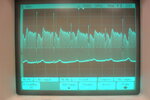
But I had actually build the circuit shown in the datasheet of INA321 and had a signal from it
ECG signal.JPG
high pass cut off =1.59hz
low pass cut off = 23hz
however, i dont understand why there is still 50hz from the power line
and actually I only need the R-wave for time reference but it look nicer for my project if i got a good ECG signal

Signing off CaptainSpock
 

Good morning Captain,

I do not think you have a 50 Hz power line problem,
otherwise it would be visible as a baseline distortion
on your oscilloscope image. Sorry.

Please read the article mentioned in the link.

Instrumentation Amplifier - Single Supply - INA321 - TI.com

Before you get any further, please connect a 4K7 resistor
across your 100K0 input resistors and send me a new
image oscilloscope again.

What build topology do you use, strip board, pcb with
careful designed ground plane ?

Low noise caps + vishay low noise metal film resistor.

Good luck.

---------- Post added at 12:54 ---------- Previous post was at 12:51 ----------

Here is the correct link for you.

**broken link removed**

---------- Post added at 13:16 ---------- Previous post was at 12:54 ----------

Please try this link, better luck.

In case it fails again it should be :

www.intersil.com/data/an/an1308.pdf

**broken link removed**
 

I did it on a PCB
This is my design ECG circuit.png

I did some changes in the right leg drive
 

Hi Captain,

I can barely read your schematic, would you please be so kind and resend it to me, in higher resolution.

Thank you.

---------- Post added at 01:00 ---------- Previous post was at 00:50 ----------

Hi Captain:

In these parts of the world, power supplies must be made to very stringent
specification if used in a critical medical environment.

I would use a 9 volt battery, and create a virtual earth supply of +- 4.5 volts.
This should last many weeks or month. I would suggest the IC TLE2426 in a
TO-92 housing, which has a current rating of 20mA max.

On looking at your pcb, I would aim for a smaller foot print, and create plenty
of ground planes around the amp circuit. Small foot print does it.


Good luck.
 

Hi alwerner,

I think this should be clearer
ecg schematic.png

You mentioned to change the resistor values at the input of the ECG, but shouldn't ECG have high impedance input.
Regarding the power supply you suggested, I'm not really sure how to implement it. actually i was thinking of using a charge pump
for the supply.

Signning off,
CaptainSpock
 

Hi

Please wire a test resistor of 4K7 Ohms, across your items on the schematic known as ecginput-2 and ecginput-4.

As I have considerable experience in this field, please just follow my clear instructions, it just makes things
quicker for both of us. The purpose of the excercise is the establish the DC-behaviour of the circuit at
a resistance of 4K7 ohms, please prepare a number of oscilloscope image for me, thanks ... using a time
base of 20ms, 50ms, and 100 ms.

Before I spend too much time, it appear we have a number of errors- do you agree with me ?

A) R7 + R10 should remain at 2K0 - otherwise the circuit might hunts ...

B) Shield drive in the original is made of of a unity gain buffer and a comparator. it
should remain like this. Other wise I can not see how you can control the "Right Leg" ?

C) Only *** knows why you have changed the values of the active filter ?

And please in as far as the split supply goes, make it simple to yourself and
use the chip I have proposed. No charge pumps, no laser guns, simply
solid engineering.

So my friend back to the drawing board, and let have your oscilloscope images
asap.

PS:
I do not wish to shoot you down, just get your project of the ground and
help you with some super charged input.

Bye for now.
 

Hi

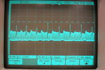
This is the image of the ECG signal after changing the input resistors
SAM_0843.JPG

The amplitude of the ECG is reduce from about 2 volts to few hundred millivolts
 

Hi:

Sorry, here is a misunderstanding. I wanted you to disconnect Left-Arm and Right-Arm ECG signal
source, and let the INA321 just look into 4K7 test resistor allone.

At this preliminary stage, I'm not interested in the AC signal, all I want to see is the "V output signal",
DC coupled, at the time base settings I had previously requested. Thanking you.

Bye for now.

---------- Post added at 22:51 ---------- Previous post was at 21:48 ----------

So for clarification:
------------------

In the original Texas Design:
---------------------------

The ECG probe is connected via 2 x 100K0 series resistors, so in order to test this circuit in my rig,
I would connect my 4K7 resistor in place of the ECG Left Arm and Right Arm electrodes.

In your design case, it would mean.
That the 4K7 test resistor, would be in place of your ECG "Left Arm" and "Right Arm" electrodes.

So what I'm looking for is a clean DC signal, coming out of "V output".

So what I would be looking out for are :

DC-Coupled test:
Do some preliminary calculations to establish the proper
operating parameters for INA321 and the "Active filter OP-Amp"

Monitor the Vr= it should remain stable.

AC-Coupled test:
Is their any noise, any beating 50 Hz

Any noise, any hunting, any spurious signals would indicate very severe problems some where.


...............................................................................................................................
Disconnect my 4K7 test resistor, and connect your ECG signal again.

Monitor the junction of R10 and R11 and see if the voltage remains stable at at
+ 2.5 volts.

Take a look withthe oscilloscope at the active filter, from either end.


Investigate where the beating comes from, which is so visable on the oscilloscope.

In my humble opinion, you do not need a "Shield drive" to get a reasonable ECG signal,
and with 3 chips and a few resistors and caps you are in the business. Shield drives
are an art form, and not for the light hearted beginners.

Think about it.

Good luck.
..............
 

Well after looking again at your circuit at some detail , it has become apparent, that you are overloading
your INA312 op-amp, by removing a vital part of the OPA336 of the Shield Driver Circuit,
namely the "DC Cancelling Cicuit".

Perhaps you would like to make yourself familiar with the shield driver circuit in the greatest possible
detail. And perhaps one suggestion, don't modify circuits you do not understand. ASK first.

Good luck:
-----------
 

Status
Not open for further replies.

Similar threads

Part and Inventory Search

Welcome to EDABoard.com

Sponsor

Back
Top