E-design
Advanced Member level 5

- Joined
- Jun 1, 2002
- Messages
- 2,014
- Helped
- 507
- Reputation
- 1,016
- Reaction score
- 408
- Trophy points
- 1,363
- Activity points
- 14,193
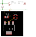
I am trying my hand at using Eagle layout software. Everything went well until I tried to transfer from schematic to PCB layout.
I found that the node connected to the emitter (red circle) of the transistor does not show up in the rats-nest (no connection where I marked in yellow) on the PCB. I used the part (BFP420) from the Infineon library. Another part from the same library makes the connection and shows up in the rats-nest. I am not sure why this happens? Is it an error in the symbol or device setup?
I have attached the library if someone want to inspect the element.
Attachments
Last edited:

