Continue to Site

Welcome to EDAboard.com

Welcome to our site! EDAboard.com is an international Electronics Discussion Forum focused on EDA software, circuits, schematics, books, theory, papers, asic, pld, 8051, DSP, Network, RF, Analog Design, PCB, Service Manuals... and a whole lot more! To participate you need to register. Registration is free. Click here to register now.

[SOLVED] Duty Cycle voltage increase

Status
Not open for further replies.

Michael Gimon

Newbie level 2
Newbie level 2
Joined
Nov 13, 2013
Messages
2
Helped
0
Reputation
0
Reaction score
0
Trophy points
1
Visit site
Activity points
16
Hello, I'm hoping someone can point me in the right direction. I'm making a square wave that can change its duty cycle. The voltage ranges from 0 to 3.75 volts but i need it to range from 0 to 5 volts. I've tried using a non inverting op amp to get that extra gain i need to achieve 0 to 5 volts but its not working. Is it something I'm doing wrong or is another type of circuit needed for a duty cycle voltage increase?
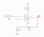

non-inverting op amp.JPG
 

Well we dont know how you design your circuit but their are many pwm chips that can do that as well
 

I agree that it doesn't make much sense to use an OP amplifier as digital level converter.
In case you want though, the OP must provide rail-to-rail output swing, LM358 doesn't.
 

I agree that it doesn't make much sense to use an OP amplifier as digital level converter.
In case you want though, the OP must provide rail-to-rail output swing, LM358 doesn't.

assuming a rail to rail op amp is used, it can be done? Is there a different circuit that could do the job better/cheaper?
 

assuming a rail to rail op amp is used, it can be done?

Yes. However, op-amps are built to handle analog signals, not digital signals--for this reason, they are pretty slow at handling digital. But yes, it can be done.

Is there a different circuit that could do the job better/cheaper?

Yes. Use a 2N7000 transistor with a 10kOhm resistor attached from its drain to +5V, and its gate attached to the 0=>3.75V digital signal. The 0=>5V signal will appear at its drain. A caveat is that your digital signal will be inverted.

If you don't have a 2N7000, you can use a 2N2222 or 2N3904 in a similar fashion. Attach a 10kOhm resistor from its collector to +5V, and a 10kOhm resistor from its base to the 0=>3.75V digital signal.
 

Is there a different circuit that could do the job better/cheaper?
A digital logic gate with TTL to CMOS level conversion capability, e.g. 74HCTxx, or a comparator.
 

Status
Not open for further replies.

Part and Inventory Search

Welcome to EDABoard.com

Sponsor

Back
Top