Continue to Site

Welcome to EDAboard.com

Welcome to our site! EDAboard.com is an international Electronics Discussion Forum focused on EDA software, circuits, schematics, books, theory, papers, asic, pld, 8051, DSP, Network, RF, Analog Design, PCB, Service Manuals... and a whole lot more! To participate you need to register. Registration is free. Click here to register now.

Dual Rail Supply for IR2104

Status
Not open for further replies.

Amr Wael

Member level 5
Joined
Jul 13, 2020
Messages
84
Helped
0
Reputation
0
Reaction score
1
Trophy points
8
Activity points
854
Hello ,
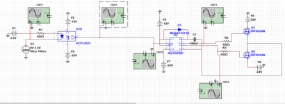
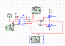
I wonder if it's possible to supply IR2104 with -12V while connecting it's ground (COM) to -24V in order to achieve a vcc of 12V relative to zero ground ?
I tried simulating it on Multisim with two IRFR024N and a 5V pulsed input but it didn't work. The output for the gate signal of the low side MOSFET remains at the -VCC while the output for the gate signal of the high side MOSFET remains at the zero.
 

Show your schematic. What is “zero ground”? Do you mean “ground”.

if you connect VCC to -12 and COM to -24, your logic input is now referenced to -24V, not zero. And VCC will be -12 V referenced to ground, not +12v.
 

I wonder if it's possible..
..the answer is given in the datasheet...

"ground" is just a name ... for a signal that usually acts as reference to (all) voltages.

Note: when you connect two 9V batteries in series there are 3 nodes. You are free ... which one you name "Ground"

Klaus
 

I am sorry for the late reply , thank you very much for your responses , Here is the schematic that's not working versus the second one that's actually working with +12V and GND.
 

Attachments

  • Capture.PNG
    Capture.PNG
    26.3 KB · Views: 109
  • working.PNG
    working.PNG
    10 KB · Views: 106

Hi,

I see.

You try to shift all the power_side_reference to -24V.

The optocoupler's supply is -19V abs. ...thus it sees +5V...so far so good.
The IR2104 ..identical with -12V ... thus it sees +12V...should work.
And also with the rest I see nothing that really is wrong. (On a quick view)

The real circuit may work.
Maybe the simulation does not work because it expects GND at COM.

Some remarks:
* all "-24V" should come from one single source and should be hard connected, otherwise you risk damage on non_synchronous power sequencing.
* most electronics designers will call your "-24V node" --> "PWR_GND" .... since it's just a name.


Klaus
 
Status
Not open for further replies.

Similar threads

Part and Inventory Search

Welcome to EDABoard.com

Sponsor

Back
Top