Vermes
Advanced Member level 4
Presented device controls the fans depending on the value of the measured temperature. It is equipped with two independent channels, with their own temperature sensors. It allows the setting with a single potentiometer all the basic values. Additionally, it is equipped with a backlit LCD display, on which all the important data is presented. The controller is designed for cooling by means of fans connected to the outputs.
Assumptions:
- independent dual-channel operation
- ability to adjust the temperature threshold at which the fan is switched, for each channel separately
- ability to adjust the hysteresis value – common for each channel
- settings resolution of 0,1 degree Celsius
- the use of transistors at the outputs of fans
- the possibility to supply by voltage of 7V-20V
- making any adjustment by potentiometer
- accuracy of 0,5 degree Celsius, while maintaining the resolution of 0,1 degree Celsius
- the whole enclosed in a slim housing
- temperature sensors protected against water
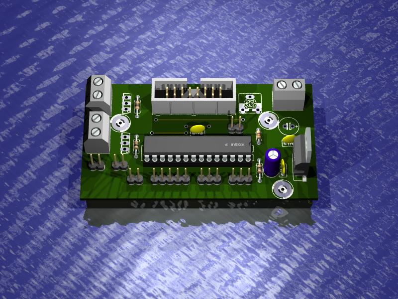
Microcontroller Atmega8 was used in this device, because it is quite cheap. The program was written in Bascom AVR. It consists of simple procedures of subtraction of numbers containing number of digits. Variable of type single was not used because it takes too much of RAM. Atmega is clocked by internal quartz resonator 8MHz. A very small amount of electronic components was attached to Atmega. In addition, Lm7805 voltage stabilizer is in the board. It allows wide range of the equipment power supply (this range can expand after the use of larger heat sink). The controller was equipped with LCD display 2x16 characters, based on hd44780. Very good Dallas sensors DS18B20 realize the function of temperature sensors. Power output system of the driver was implemented on the BD139 NPN transistors, where the maximum load is 1A (properly selected database resistor will not allow for more). Voltage on the outputs of fans is equal to the voltage that powers the system.
The following diagram of the system (only the protective diodes are missing, they are connected directly in the slots):

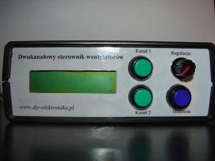
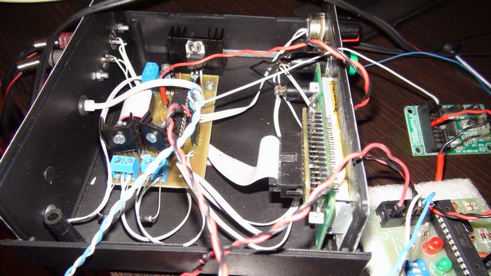
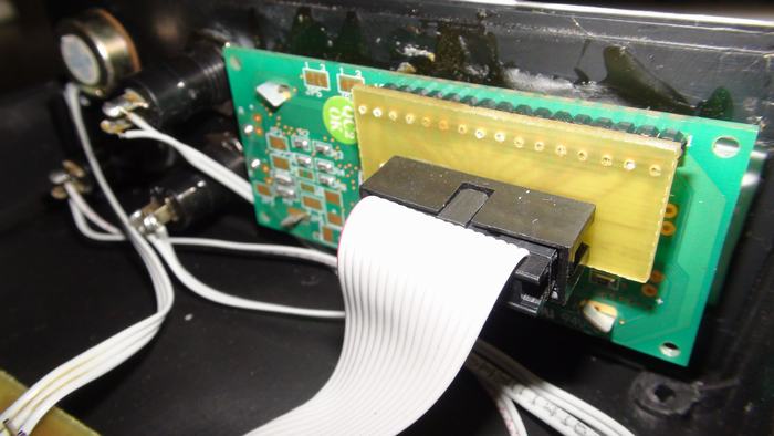
Housing:
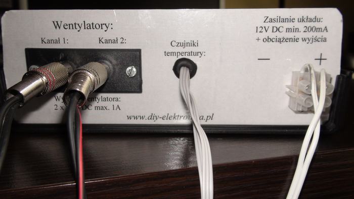
The applied housing was universal one of type Z-P4. Appropriate holes were drilled in it. The front and back panel were designed in a graphic program, printed on the laser printer and laminated after that. A small module with RCA inputs acts as slots of fans outputs. The power supply can be plugged to the back of the device. The temperature sensors are connected permanently to the controller, via a cable with a length of about 2,5m. Buttons are secured with nuts, while the LCD display was glued to the front panel. The driver board is attached to the housing on metal distances, which are screwed to the bottom with nuts.
Start, first settings:
While starting, the microcontroller checks if two temperature sensors are plugged (if not, the controller does not start and appropriate message is displayed on the LCD), and then the EEPROM is checked – if there is no data, or the data is incorrect, appropriate message is displayed, which informs that you should set the parameters of operation of the device, and then continuous its work.
You can make settings in a really simple way, using three buttons and a potentiometer. Two buttons are responsible for regulating the threshold temperature – respectively for channel 1 and 2. The third button (blue) is responsible for regulating the value of temperature hysteresis. The potentiometer is universal – it can be used for regulation of all values. By pressing the “Channel 1”, you begin to regulate the threshold temperature of the first channel. It can be set with a potentiometer, after a suitable set you can again press the “Channel 1” - it is followed by recording the values to the EEPROM, and a return to normal operation. Similarly, you can set the other two parameters. Hysteresis can be set to 0-4 degrees Celsius, while maintaining the resolution of 0,1 degree Celsius, while the value of the threshold temperature is in the range 10-30 degrees Celsius.
Operation:
The principle of operation is the following (each channel separately):
Temperature measurement is performed every 1s, when the temperature exceeds the set threshold, then voltage appears at the output, the fan starts cooling. The fan operation continues as long as the value of the measured temperature does not drop below a set temperature threshold minus the hysteresis value – then the fan is turned off.
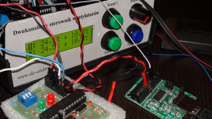
LCD display:
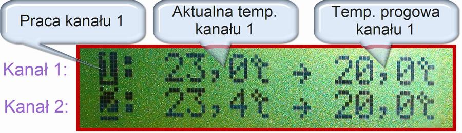
During normal operation, the following data is presented on the display:
- state of the corresponding channel output – the number on a black background means working channel, while the number without a background means that the channel is not working. The number of the channel is presented by precisely this number.
- current temperature of each channel.
- the threshold temperature of each channel
- hysteresis value is displayed every 2 minutes for 2 seconds
Additionally, the LCD display is very useful while setting the threshold temperatures – then the set temperature is presented by the potentiometer.
Gallery:
Link to original thread (useful attachment) – Dwukanałowy sterownik wentylatorów