Continue to Site

Welcome to EDAboard.com

Welcome to our site! EDAboard.com is an international Electronics Discussion Forum focused on EDA software, circuits, schematics, books, theory, papers, asic, pld, 8051, DSP, Network, RF, Analog Design, PCB, Service Manuals... and a whole lot more! To participate you need to register. Registration is free. Click here to register now.

DS18b20 reading too high - 8051

Status
Not open for further replies.

FoxDie

Newbie level 5
Joined
Apr 7, 2013
Messages
10
Helped
0
Reputation
0
Reaction score
0
Trophy points
1,281
Activity points
1,365
I need your help and support, as I'm out of ideas.
I'm working on simple micro-temperature controller project, as this is the first one for me in uC.

I'm using at89s52 with 11.0592 MHz, plus the DS18b20 & LCD 16x2.
And I'm compiling c code using Keil uVision V4. Below is the whole code I'm using.

My hardware connection:
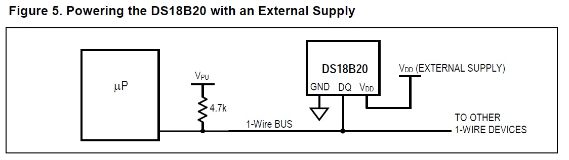
DS18B20: DQ = P3.3 with 4K7 connect to Power Vdd

LCD: RS = P3.6
RW = P3.5
E = P3.7
DataLine = P1

My problem here is with the temperature reading is stuck at too high reading 655.30 *C. And the reading doesn't change at all.
I wonder why? I have troubleshoot the coding, but nothing seems wrong with the code. I'm suspecting a hardware issue, but I'm not very experience with such connection.

So, please help resolve this problem. And thank you in advance.

Code:
//DS18B20 Code: DQ = P3.3
#include<intrins.h>
#include<AT89X51.H>
#include<math.h>
#include<stdio.h>


//LCD code: RS = P3.6 -- RW = P3.5 – E = P3.7 – DataLine = P1


sbit RS = P3^6; 
sbit RW = P3^5; 
sbit E = P3^7; 
sbit DQ = P0^1;

void init(void); 
void writeCmd( unsigned char a ); 
void writedat(unsigned char b );
void Delaylcd(void);
void sendstring(unsigned char *b);

void init() 
{ 
 	writeCmd(0x01);
 	writeCmd(0x38);
 	writeCmd(0x0C);
 	writeCmd(0x06);
}

void writeCmd(unsigned char a)
{
 	RS = 0;
 	P1 = a;
 	RW = 0;
 	E = 1;
 	Delaylcd(); 
 	E = 0;
}

void writedat(unsigned char b)
{
 	RS = 1;
 	P1 = b;
 	RW = 0;
 	E = 1;
 	Delaylcd(); 
 	E = 0;
}

void Delaylcd()
{
 	unsigned char j,k;
 	for (j=0; j<255; j++)
 	for (k=0; k<5; k++);
}

void sendstring(unsigned char *c)
{
 	while(*c) //till string ends
 	writedat(*c++); //send characters one by one
}


//sbit DQ=P3^3;
unsigned char tmp1, tmp2;
unsigned char buffer[16];
unsigned char cdis1[16] = {" TEMPERATURE: "};
unsigned char cdis2[16] = {"C"};

void delay(int useconds);
unsigned char ow_reset(void);
unsigned char read_bit(void);
void write_bit(char bitval);
unsigned char read_byte(void);
void write_byte(char val);
void get_temp(void);
float Temp_convert ();


void delay(int useconds)
{
 	int s;
 	for (s=0; s<useconds;s++);
}

unsigned char ow_reset(void)
{
 	unsigned char presence=0;
 	DQ = 0; //pull DQ line low
 	delay(29); // leave it low for 480us
 	DQ = 1; // allow line to return high
 	delay(3); // wait for presence
 	presence = DQ; // get presence signal
 	delay(25); // wait for end of timeslot
 	return(presence); // presence signal returned
} // 0=presence, 1 = no part 

unsigned char read_bit(void)
{
 	unsigned char i;
 	DQ = 0; // pull DQ low to start timeslot
 	DQ = 1; // then return high
 	for (i=0; i<3; i++); // delay 15us from start of timeslot
 	return(DQ); // return value of DQ line
}

void write_bit(char bitval)
{
 	DQ = 0; // pull DQ low to start timeslot
 	if(bitval==1)
	{
		DQ =1; // return DQ high if write 1
	}
 	delay(5); // hold value for remainder of timeslot
 	DQ = 1;
}


unsigned char read_byte(void)
{
 unsigned char i;
 unsigned char value = 0;
 	for (i=0;i<8;i++)
 	{
 	 if(read_bit())
	 {
		 value|=0x01<<i; // reads byte in, one byte at a time and then shifts it left.
		            	   // If DQ=0, skip, if DQ=1 execute shifting of "1" then OR.
	 }
 	 delay(6); // wait for rest of timeslot
 	}
return(value);
}// Delay provides 16us per loop, plus 24us. Therefore delay(5) = 104us

void write_byte(char val)
{
 	unsigned char i, temp2;
 	for (i=0; i<8; i++) // writes byte, one bit at a time
 	{
 		temp2 = val>>i; // shifts val right 'i' spaces
 		temp2 &= 0x01; // copy that bit to temp
 		write_bit(temp2); // write bit in temp into
 	}
 	delay(5);
}

void get_temp(void)
{ 
 	ow_reset();
 	write_byte(0xCC);
 	write_byte(0x44);
	delay(5);
 	ow_reset();
 	write_byte(0xCC);
 	write_byte(0xBE);
 	tmp1=read_byte();
 	tmp2=read_byte();
}

float Temp_convert ()
{
 	float f_temp1;
 	bit flag;
 	unsigned int uint_temp;
 	uint_temp=tmp2;
	uint_temp=uint_temp<<8;
 	uint_temp=uint_temp|tmp1;
 	flag=uint_temp&&0xF800;
 	
 	if(flag == 0xF800)
	{
 		f_temp1=(~uint_temp+1)*0.0625;
 		f_temp1= f_temp1*-1;
 	}
	
	else if(flag == 0)
 	{
 		f_temp1= uint_temp*0.0625;
 	}
  	return f_temp1;
}

void main()
{ 
	float f_temp2;
 	unsigned int uint_temp2;
	unsigned char j;
 	init();
 	writeCmd(0x80);
 	sendstring(cdis1);
 	writeCmd(0xCC); 
 	writedat(0xDF);
	writeCmd(0xCD);
	sendstring(cdis2);
 	

 	while(1)
 	{
 		get_temp();
	 	f_temp2= Temp_convert();
 	 	uint_temp2 = f_temp2 * 100;
 	 	sprintf(buffer,"%3d.%2d",uint_temp2/100,uint_temp2%100);
		//sprintf(buffer,"%3.4f\r\n",f_temp2);
		writeCmd(0xC2);
 	 	sendstring(buffer);
 		for(j=0; j<1000; j++);
 	 	uint_temp2=0x00;
 	}
}
 

It's impossible to have a reading ending in ".30".

Read the ROM code out of the device and see if the 8-bit family code matches. Should be 28h.
 

I'm not really sure I understood you very well, but here is what I did:
I tried to display Byte 0"LSB" & Byte 1"MSB" of the Scratchpad directly without any conversion. And I got this strage reading: t2=ff00 t1=ff00

The code I use to display those reading is:
Code:
while(1)
 	{
 		get_temp();
	 	f_temp2= Temp_convert();
 	 	uint_temp2 = f_temp2 * 100;
		sprintf(buffer,"t2=%x",tmp2);
		writeCmd(0xC0);
 	 	sendstring(buffer);
		sprintf(buffer," t1=%x",tmp1);
 	 	sendstring(buffer);
 		for(j=0; j<1000; j++);
 	 	uint_temp2=0x00;
 	}
 

Yes, I'm following the datasheet. Actually, I got the ds18b20 code from their website. And I edited a little bit.
HTML:
http://www.maximintegrated.com/app-notes/index.mvp/id/162

And regarding the Skip ROM, I'm doing it as well. See the function in the below code:
Code:
void get_temp(void)
{ 
 	ow_reset();
 	write_byte(0xCC);  // Skip ROM
 	write_byte(0x44);  // Start Conversion
	delay(5);
 	ow_reset();
 	write_byte(0xCC);  // Skip ROM
 	write_byte(0xBE);  // Read Scratch Pad
 	tmp1=read_byte();
 	tmp2=read_byte();
}

And regarding the previous reading t2=ff00 t1=ff00
If you take t2=ff & t1=ff
then the decimal of ffff=65535 which is almost corresponding to the original reading I was previously getting=65530
 

I had a small question:
Why do I need a pullup resistor connected to a 5V and to DQ pin when I'm already using an external supply on the Vdd pin?

4920694900_1365504672.jpg
 

I have just did the simulation at Proteus using my code and my hardware design.
And the result was the same as in reality :shock: which means that I'm definitely doing something big wrong, and also proves my hardware good functionality.
Somehow, I'm pleased but still not yet fully.

Please have a look at the graph and feed me back.

Proteus_Design_sm.jpg
 

65530, or 65535, or whatever, is not the decimal value...see the datasheet for how to convert it.

The DQ line needs a pullup resistor because the device cannot drive the line high. It's also part of the 1-wire spec. It has an open drain output.

For now, skip the temperature reading. Just read the ROM until you figure out what you need to fix to get the correct value.

But after seeing your recent post your schematic may have illuminated the problem. The DS18B20 needs at least 3V to work. Why aren't you powering it from the same Vdd that runs the 8051? It also should share the same ground.
 

Sorry for the misconfiguration in the schematic. Actually, It's supplied by 5V, from the same source for the uC.
I've just used this software, and trying to understand its features.
I modified the schematic:
proteus_design2_sm.jpg
My question, would it make any difference if I supplied the DS18b20 using an external power?
 
Last edited:

Well, as long as the power supplied to the DS18B20 is within spec it should be okay in theory, but the sensor and the uC will both be creating signals with reference to ground. So they should both at least share the same ground, otherwise you could get weird problems.

If you wanted to use separate power supplies for the sensor and the uC it would probably be best to use an optoisolator. But I would first concentrate on getting it all to work from the same supply.
 

I will try to read the ROM [33h], but what should I do with it?
I understand that it is the unique 64-bit code, but what are the benifits?
 

Have you tried increasing the delays? I think that when the DS18B20 sends 0xffff it means that he didn't have enough time to sample the temperature.
 

Uhhh, unfortunately, I'm getting all ffff for Read ROM.
Below is the code I used for reading ROM.

I guess I may not have a good initialization for the ds18b20, to begin with.
Is it a problem with the temperature sensor? or is it a delay issue? I'm not really sure.

Pictou
Thank you for your reply. can you please advise on how much delays I should try especially for the initialization sequence?

Code:
void Read_ROMCode(void)
{
int n;
char dat[9];
sendstring(buffer);
ow_reset();
write_byte(0x33);
for (n=0;n<8;n++){dat[n]=read_byte();}
sprintf(buffer,"\n%X%X%X%X\n",dat[7],dat[6],dat[5],dat[4],dat[3],dat[2],dat[1],dat[0]);
sendstring(buffer);
}

- - - Updated - - -

I have done a small test for the ds18b20 initialization sequence "ow_reset()" using the below code.
Again, the result was bad. I received 1 for "ow_reset()" where I should have received 0, to make sure initialization is complete.

Correct me if I'm wrong?

Code:
unsigned char cdis1[16] = {" OK "};
unsigned char cdis2[16] = {" Fail "};
void main()
{ 
	unsigned char chk=0;
	unsigned char j;
 	init();

 	while(1)
 	{
		writeCmd(0xC0);
		chk=ow_reset();
		if(!xchk)
		{
			sendstring(cdis1);
		}
		else
		{
			sendstring(cdis2);
		}
 		for(j=0; j<1000; j++);
 	}
}
 

Okay I'll try to help you from the beginning. It might not be the problem but my delays are a little higher than yours.


For reset sequence : Your code will be in quotation
unsigned char ow_reset(void)
{
unsigned char presence=0;
DQ = 0; //pull DQ line low
delay(29); // leave it low for 480us
DQ = 1; // allow line to return high
delay(3); // wait for presence
presence = DQ; // get presence signal
delay(25); // wait for end of timeslot
return(presence); // presence signal returned
} // 0=presence, 1 = no part

Assuming delay(29) is 480 us, (you need to make sure of that with an oscilloscope for example). For the second delay, instead of delay(3) I would make a delay of 100us which would become delay(7).
So new code would be the same thing except delay(3) becomes delay(7) but make sure that the delays are correct (with oscilloscope if you can).


For read bit, you had
unsigned char read_bit(void)
{
unsigned char i;
DQ = 0; // pull DQ low to start timeslot
DQ = 1; // then return high
for (i=0; i<3; i++); // delay 15us from start of timeslot
return(DQ); // return value of DQ line
}

Okay for this part I'm not entirely sure what your code means. the only microcontroller I used were PIC models. So I'm going to ask you several questions :

The datasheet says : "read time slots is initiated by the master device pulling 1-wire bus low for a minimum of 1us and then releasing the bus".
So after pulling the bus low which is done by DQ = 0; you need to add a delay of 1us (make it 2).

And then you must release the bus.
Does your code : DQ = 1; // then return high, release the bus or put it high ?
By releasing the bus, I mean that the pin becomes an input pin and not output. Does your code do that? Because the way it's coded right now makes me feel like you are actually setting the level of the bus instead of releasing it.

Your delay of 15us is wrong. The datasheet says that
Output data from the DS18B20 is valid for 15μs after the falling edge that initiated the read time slot. Therefore, the master must release the bus and then sample the bus state within 15μs from the start of the slot.

So you must sample the data before 15us. I chose 8us delay, see "code below".

Then after collecting the data from the bus return(DQ); // return value of DQ line, you must add more delays because the datasheet says :

All read time slots must be a minimum of 60μs in duration


The new code should be (as I'm not sure about what you are doing I will write it in algorithm):

unsigned char i;
Set the pin connected to the 1-Wire as an output
Set the level of that pin to low (DQ = 0; // pull DQ low to start timeslot)
Delay of 2 us
Release the bus by making the pin an input
Delay of 8us
Read the data on the PIN
Delay enough to reach 60us as the datasheet says that all read time slots must last at least 60us. You can wait for example 50us (50 + 8 + 2 = 60). Make sure that your delay is correct again.
Return data line (return(DQ); // return value of DQ line)

Write bit is wrong too, you need to read the datasheet closely. I'll let you work the code a little, I can't give you the answers right away you won't learn anything. If you rework your write_bit code and think it's correct post it on the forum and I'll check it as soon as I can.


EDIT : Yes reset should return 0.

EDIT 2 : Test reset first, if it still doesn't work let me know, it's useless to do the rest if reset doesn't work.

EDIT 3 : Oh and the error in read bit is why you kept reading 0xffff, you didn't release the bus but actually set the bus to "1" all the time.
 
Last edited:

Oh, at last I'm getting some reading.
First of all, thank you so much for keeping up with me. You responses had me thinking and realize my problems.
For your question: the delay, reset, read bit, write bit, read byte, and write byte are al provided by the sensor website for 8051 uC, as I said in one of above post.

Anyway, after the initialization and read_ROM didn't work, I thought there could be something wrong with my sensor connection.
So, I tried every possibility until I got the initialization and read_ROM working fine.
At the end, the working connection are:
Vdd and GND are short-circuited to the ground.
DQ = uC port with 4K7 connect to Power supply.


I also did read_ScratchPad, and had a very good result as expected per the datasheet:
The default result is: 1C100CFF7F464B0550

But, when I tried to get some reading, the conversion were not working at code write_byte(0x44)
Code:
		ow_reset();
		write_byte(0xCC); //Skip ROM
		write_byte(0x44); // Start Conversion
		delay(5);
		ow_reset();
		write_byte(0xCC);  // Read Scratch Pad
		Read_ScratchPad();

I might need to increase the delay or something. Please your advice.
 

I added 750ms delay after conversion and replaced the pullup resistor to 1k as suggested by some experimenter. And it worked :grin:
I got some reading, but there is a little problem. The reading is about (1920)h to (18C0)h
In this reading, I'm not able to read the 4 sign bits of Byte 1 which is supposed to be Zero.
And also, I shouldn't get zero at the end. It is useless as it not changing at all.

Below is the code I'm using to display my output. Where do you think is the error?

Code:
void Read_ScratchPad(void)
{
	int j;
	char pad[10];
	write_byte(0xBE);
	for (j=0;j<9;j++){pad[j]=read_byte();}
	sprintf(buffer,"%X%X",pad[1],pad[0]);
	sendstring(buffer);
}
 

See mikroC DS18B20 example project C Code. If you install the demo compiler you will get the example file and you can also find it at libstock.
 

Status
Not open for further replies.

Similar threads

Part and Inventory Search

Welcome to EDABoard.com

Sponsor

Back
Top