Vermes
Advanced Member level 4

Transistors IGBT GB100TS60 of parameters: 100A, 600V, 60kHz were used in this device. They were ideal to realize DRSSTC 1.
Book “DRSSTC – Building The Modern Day Tesla Coil” may be useful.
In this DRSSTC there are: primary winding, copper pipe 6mm, analogical dimensions in secondary winding. The lower toroid is half bigger, MMC from FKP1 1600VDC/960VAC 22 nf and 68 nf condensers, connected properly, which give battery of 3200V 455nF.
Primary winding is made of copper pipe. It is compound with eight plates cut from milky plexiglass, thickness of 2mm. Spacings between the coils are 5mm. Additionally, a protective coil is on the plates, to protect the primary winding. The protective coil should be in the shape of omega.

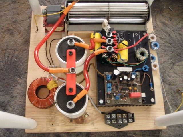
Four one-directional diodes 1.5KE110 connected in series work as transils, so that the power which can be lost by them, could quadrupled. Condensers for 400V 15uF MKP – as seen in the pictures, were used as snubbers (condensers which smooth/remove the pins created during the switching the transistors). The connections should be possibly the shortest. Diodes TVS on gates are 33V, zener diodes also 33V, gate resistors 3,2Ohm. The rise time of 200-300nS. Control - two large cores GDT TN-36, material used: 3E25. GDTs with 12 coils, the primary winding is doubled to reduce the impedance. Thus we obtain 1:1 (primary) : 1:1 (secondary). The secondary windings are in relation to the original secondary 1:1:1. There is about 30V on gates, the gate trench reaches TVS range of working – about 33V.
Thick lines between the resonant part (primary resonant circuit) and the bridge. Cables of relatively large cross section of 10mm^2 in thick red insulation. M6 ring connectors finish each wire. They were soldered over the cooker and a thermal pipe was put on them so they look aesthetically. The contact surface of each component in the resonant block (both primary and secondary) should be as large as possible, and the strongest pressure. Transistors were placed on a large radiator. In order to stuff deposited warn air from between the ribs, a blower from tanning bed was used. Of course, every connection should be as short as possible, and between electronics and bridge, the connections should be twisted together very hard. The driver system is the classic, except that the small changes introduced on UCC37321/22 and TC4422.
Because 9 A trench from TC4422 is very much, and the capacities of the IGBT gates are generally smaller than the IRFP460, two IGBT blocks from two TC4422 drivers need to be actuated.
Current limiter OCD was implemented classically, but it has a couple of disadvantages. Exceeding 2V and starting at the beginning of 0,2-0,5V is not advised.
The full bridge is another part of the device. Two blocks of transistors containing half-bridges form a full bridge. The control system is mounted on a radiator, so the connections are as short as possible.
Transformer powering the driver is a small toroid 100VA 2x12. Windings are connected in series. Old driver and GDTs are shown in the picture. Four tubes from the water and threaded rod are parts of the whole mounted. Height is about 40cm.
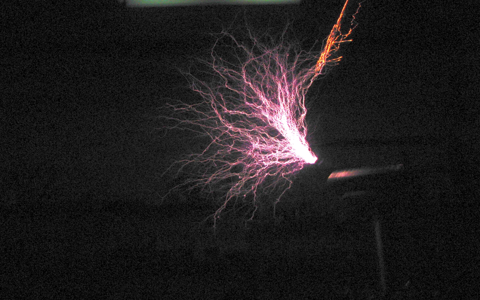
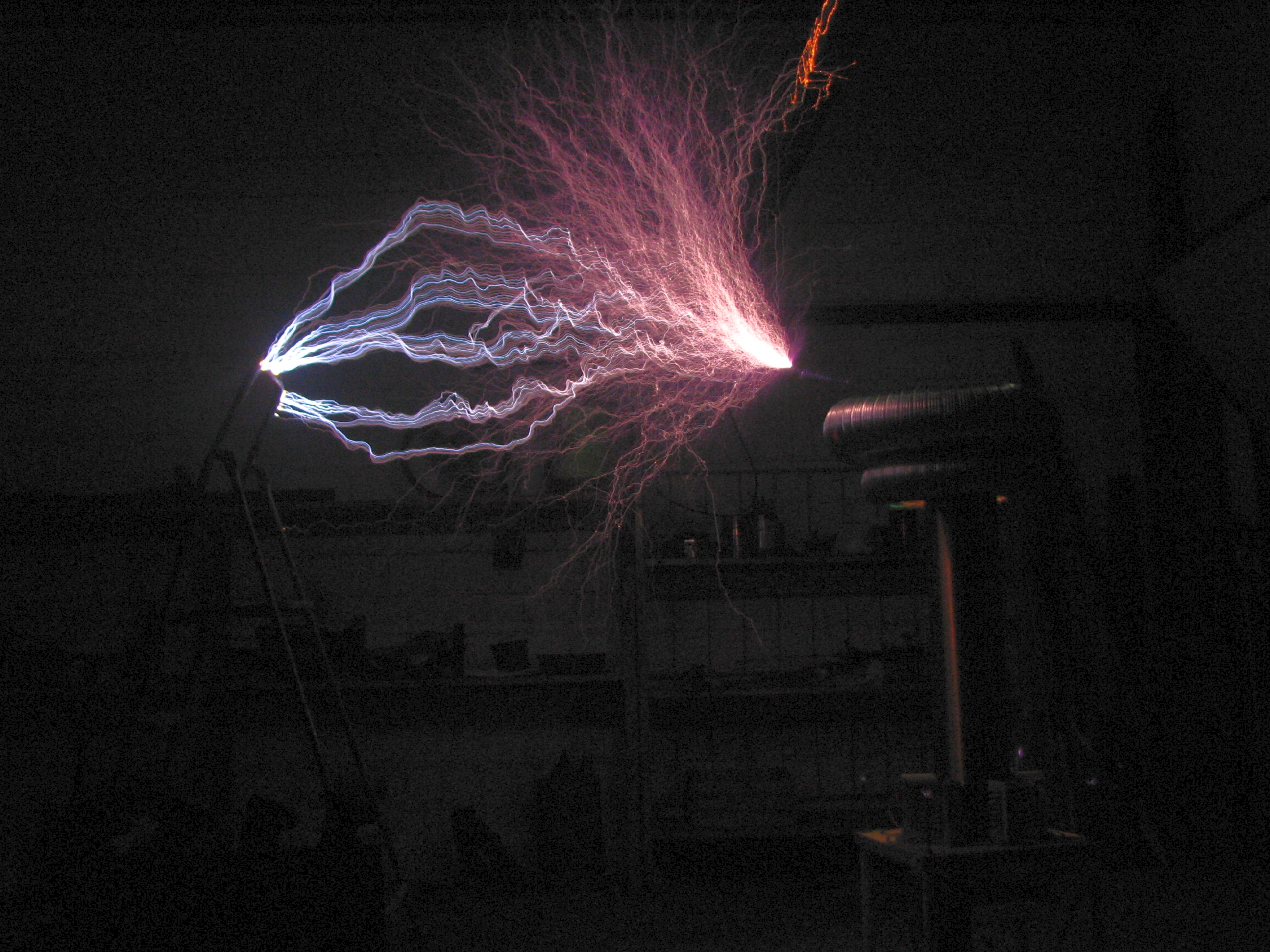
The maximum lightning was about 2 meters.
This is a sample of some changes that can be done to the project:
Link to original thread – DRSSTC - kolejna Tesla na Elektrodzie