Continue to Site

Welcome to EDAboard.com

Welcome to our site! EDAboard.com is an international Electronics Discussion Forum focused on EDA software, circuits, schematics, books, theory, papers, asic, pld, 8051, DSP, Network, RF, Analog Design, PCB, Service Manuals... and a whole lot more! To participate you need to register. Registration is free. Click here to register now.

Drive Triac without optocoupler with Positive Power Supply

Status
Not open for further replies.

Piyush Verma

Newbie level 4
Joined
Oct 8, 2014
Messages
5
Helped
1
Reputation
2
Reaction score
1
Trophy points
3
Activity points
28
Hello All,

I am trying to drive triac with Positive Power supply.

With positive power supply it should be possible to drive triac in Q1 and Q4.

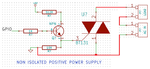
Here is the circuit I am using.

But triac is not triggering. I have checked in oscilloscope the signal on gate looks good enough.

untitled.png

I really need your expert suggestion to troubleshoot issue.
 
Last edited by a moderator:

The transistor circuit that drives the gate also should connect to pin 1. Yours does not connect to pin 1. Then your connection to the gate is floating and does nothing.
The transistor in an opto-isolator connects to the gate and also connects to pin 1 of the triac.

How do you prevent somebody (or yourself) from being electrocuted without using an opto-isolator?
 

Attachments

  • triac.png
    triac.png
    138.3 KB · Views: 1,274
I agree with Audioguru that the trigger voltage must be supplied between main terminal 1 and gate.

Secondly most standard triacs are of the three quadrant type and can't be triggered in Q4. If you want to trigger this type with a DC voltage, it must be negative. Usually the positive supply is connected to terminal 1 to achieve this.
 

Thank you very much Audioguru for pointing. I refer to original reference schematic and your suggestion match with it. you are genius.

I am aware of high voltage issue. While designing I will be careful for that. In Final application use case this pcb will reside inside switch board. so no risk.

Thanks again I will test it tomorrow and update here.

- - - Updated - - -

I agree with Audioguru that the trigger voltage must be supplied between main terminal 1 and gate.

Secondly most standard triacs are of the three quadrant type and can't be triggered in Q4. If you want to trigger this type with a DC voltage, it must be negative. Usually the positive supply is connected to terminal 1 to achieve this.

You are right. Many triac not support Q4, But I am using bt131 which support Q4 also.

My first preference was to use negative power supply as it require less current to trigger triac. I am using viper12a as non isolated buck mode "CD00159053.pdf" application note .

and no idea how to achieve negative power supply with that.

If any suggestion that would be great. It looks I am crossing the forum rule I can't ask new question about viper12a in it so latter I will create new thread.
 

Thanks Audioguru & FvM for suggestion.

After apply Audioguru circuit triac is always on.

Even when I remove Transistor triac is always on because of pull down resistor even when pull down resistor is 1M. IN this state I can see a high frequency noise on gate approx 18us pulse don't know coming from where.

When I remove pull down resistor triac is off.

When I use transistor without pull down still triac is always on. in this state I can see a little noise on Gate pin which should cause triggering triac.

Any suggestion would be great

- - - Updated - - -

Sorry for my mistake.

Now it works.

A1 & A2 was swapped.
 
Status
Not open for further replies.

Similar threads

Part and Inventory Search

Welcome to EDABoard.com

Sponsor

Back
Top