Sink0
Full Member level 6
- Joined
- Nov 25, 2009
- Messages
- 390
- Helped
- 37
- Reputation
- 74
- Reaction score
- 30
- Trophy points
- 1,308
- Location
- Sao Paulo, Brazil
- Activity points
- 4,186
Hi, i need to drive a logic level mofet from a LPC1758 microcontroller. For the mosfet i will be using 3.3V is too low so i will need 5V at the gate.
As a initial idea i will be using a npn transisor to drive the mosfet. I will get an inverted logic, but that is not a big problem.
My doubt is about the initialization of the system. During the MCU boot, the pins will be inputs with a internal pull-up. I could not find on the manual how weak or strong is that pull-up, so i dont know if i will get enough current to turn on the NPN (MMBT3904 for instance). If that does not happen the FET will be ON and the load active, for a few microseconds or even miliseconds, what is not good.
In order to solve that problem i was thinking on using an external pull-up resistor to ensure the that the transistor will be conducting, so the FET will be OFF.
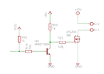
The circui would be the following (the diodes at the FET and the load are missing here, and VCC is 3.3V)

Is that a good idea? Any other better solution?
Thank you!
As a initial idea i will be using a npn transisor to drive the mosfet. I will get an inverted logic, but that is not a big problem.
My doubt is about the initialization of the system. During the MCU boot, the pins will be inputs with a internal pull-up. I could not find on the manual how weak or strong is that pull-up, so i dont know if i will get enough current to turn on the NPN (MMBT3904 for instance). If that does not happen the FET will be ON and the load active, for a few microseconds or even miliseconds, what is not good.
In order to solve that problem i was thinking on using an external pull-up resistor to ensure the that the transistor will be conducting, so the FET will be OFF.
The circui would be the following (the diodes at the FET and the load are missing here, and VCC is 3.3V)

Is that a good idea? Any other better solution?
Thank you!