mbabayan
Newbie level 3
Hello,
I'm trying to design a circuit that would produce an output pulse (.5-1 seconds) when double pulse on the input is detected with a time gap of <=.5 seconds or so.
This is supposed to be a gadget that activates a garage opener on the double-tap of the "flash-to-pass" switch on the motorcycle. Devices like this are available commercially, but I'm not paying $100 or so when I can build it")
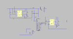
I've came up with the following design in LTSpice, but I'd really appreciate an opinion on it before I proceed with prototyping.
It is based on a timer and a counter - when input pulse is detected, 555 in monostable mode gets triggered, releasing the reset on the counter. If a subsequent pulse is detected withing the output pulse of the monostable, it will switch the counter into subsequent position, thus activating second monostable to produce an output pulse of preset duration. Otherwise, the first monostable will "reset", disabling the counter. Does this make any sense whatsoever?
The circuit along with the simulation plot is attached.
Any feedback is greatly appreciated.
-MB
I'm trying to design a circuit that would produce an output pulse (.5-1 seconds) when double pulse on the input is detected with a time gap of <=.5 seconds or so.
This is supposed to be a gadget that activates a garage opener on the double-tap of the "flash-to-pass" switch on the motorcycle. Devices like this are available commercially, but I'm not paying $100 or so when I can build it
I've came up with the following design in LTSpice, but I'd really appreciate an opinion on it before I proceed with prototyping.
It is based on a timer and a counter - when input pulse is detected, 555 in monostable mode gets triggered, releasing the reset on the counter. If a subsequent pulse is detected withing the output pulse of the monostable, it will switch the counter into subsequent position, thus activating second monostable to produce an output pulse of preset duration. Otherwise, the first monostable will "reset", disabling the counter. Does this make any sense whatsoever?
The circuit along with the simulation plot is attached.
Any feedback is greatly appreciated.
-MB