Welcome to our site! EDAboard.com is an international Electronics Discussion Forum focused on EDA software, circuits, schematics, books, theory, papers, asic, pld, 8051, DSP, Network, RF, Analog Design, PCB, Service Manuals... and a whole lot more! To participate you need to register. Registration is free. Click here to register now.
I made a simulation of your schematic. I can't help but believe something is missing somewhere. Perhaps near the resistor?
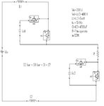
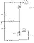
Your double boost converter consists of two similar halves. They are arranged in series. And it makes me wonder, what did a single converter start out looking like?
From my understanding of dual interleaved boost converters, they have two coils, arranged in parallel rather than in series.
Nothing is said about interleaved operation. According to the schematic, both converters are operated in phase. So as a a first analysis step, you can cut the circuit into two identical halves.
The usage of the term CCM seems questionable for a synchronous switcher, however.
Just a riddle. The resistor is meaningless for circuit operation.
It seems like you didn't yet make the effort to understand the circuit operation. But this is just the purpose of these excercise problems, even if they are confusing.
Dear FvM, which resistor is meaningless? The resistor in second image? If you operate the upper and lower boost converter, you will get a AC drop across the resistor..
Please don't hold us responsible for unclear or confusing excercise problems. I still doubt that the term CCM is correct at all. In a synchronous switcher, one or the other path is always conducting.
If you mean to understand what CCM means for a synchronous switcher, please let us know.
continuous conduction mode (CCM). What is the required value of R to operate the boost converter in CCM (boost converter inductor current should be in continuous).
For a synchronous switcher or normal boost converter the resistor is connected across the capacitor so it is easy to get the value of R to operate the converter in CCM. But here resistor is connected between two boost converters, so facing difficulties in finding the R value. If you get any idea please help me.
This site uses cookies to help personalise content, tailor your experience and to keep you logged in if you register.
By continuing to use this site, you are consenting to our use of cookies.