cupoftea
Advanced Member level 5
Hi,
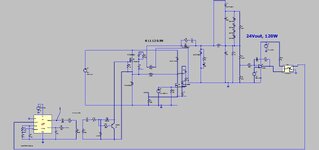
Why do they use pulse transformer output for top and bottom?
 e2e.ti.com
It just means more components.
You could pllel those two output coils and get lower leakage to drive just the top FET with.
Why do they use pulse transformer output for top and bottom?
UCC28511: Two transistor forward converter - Power management forum - Power management - TI E2E support forums
Part Number: UCC28511 Dear all, I am designing PFC and two transistor forward converter with UCC28511 controller. PFC works well, but I have problem with forward
e2e.ti.com
It just means more components.
You could pllel those two output coils and get lower leakage to drive just the top FET with.