Continue to Site

Welcome to EDAboard.com

Welcome to our site! EDAboard.com is an international Electronics Discussion Forum focused on EDA software, circuits, schematics, books, theory, papers, asic, pld, 8051, DSP, Network, RF, Analog Design, PCB, Service Manuals... and a whole lot more! To participate you need to register. Registration is free. Click here to register now.

Door Chime Sequencer Problem

Status
Not open for further replies.

holabr

Member level 2
Member level 2
Joined
Feb 12, 2010
Messages
46
Helped
1
Reputation
2
Reaction score
1
Trophy points
1,288
Location
USA
Activity points
1,719
I have a set of vintage door chimes that uses an electro-mechanical sequencer to activate a series of plungers to strike the chimes. The problem is the mechanism uses a low rpm motor to sweep a set of contacts over traces on a PC board to sequencially ring the chimes. It has worn to the point that it is no longer consistently rings the chimes. I'd like to build an electronic replacement and have a few questions.

1) What would be the best way to convert the 16 VAC pulse when you press the doorbell button into something the circuit can use to start the sequence?

2) I'm thinking of using a PIC to drive the circuit. This would be my first attempt. Is this overkill or would hard logic be better?

Because of the existing wiring in the house and the fact that the plungers require the 16 VAC transformer, changing over to some other power supply is not an option.

I'd appreciate any direction and examples of similar circuits as a starting point.
 

I imagine it will be hard to fabricate mechanical replacements for such a mechanism.

Is the PC board worn? Can you repair it by soldering wires where the copper traces are worn?
Or are the moving contacts worn? Can you solder wires on as replacements?

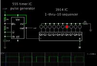
To do it electronically, a 3914 IC is a popular way to turn on 10 outputs, one at a time in sequence.

Screenshot showing a simplified illustration of the concept:


The output pins provide DC, not AC. So regarding how to deliver power to each of the plungers in turn, that could be a challenge. Perhaps it will be sufficient if you provide a single strong jolt to each one? Then it can be DC power. The 3914 outputs are probably too weak. Their signals can be amplified with a single transistor. You would need several transistors.

If the plungers require AC, then a relay is probably the simplest way to activate them. You would need several relays if you go that route.

To provide DC power for the 555 and 3914, you can build a common type using a diode bridge and smoothing capacitor. Its volt level may be too high, in which case you must regulate it down to a usable level.
 

I would suggest that you use microcontroller as the "sequencer" and small triacs as the driving elements for plungers.
Give some more details on your door chome, how many plungers?
 

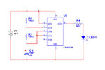
I have been working in Multisim to understand how I could use a 555 timer and a 4017 counter to solve my problem. I seem to be having a problem with the LEDs just flickering. I simplified and isolated the circuit to just the 555 part of the circuit and still the LED flickers in simulation. I tried different resistor and capacitor values but it doesn't change anything. Any ideas what I am doing wrong? (see attached)
 

Attachments

  • test.jpg
    test.jpg
    29.1 KB · Views: 98

I simplified and isolated the circuit to just the 555 part of the circuit and still the LED flickers in simulation.

See if it works better if you install a ground somewhere. Some simulators will not execute without a ground.

I find that the longer the interval the action takes to happen, the longer I must set the time-step.

Your circuit looks okay. The 555 is a popular and easy-to-use chip.

As an alternative, look in your simulators Examples folder, to see if there is a 555 pulse generator you can run.
 

Thanks, I installed the ground and the simulation works fine now.

There are 4 plungers that play a total of 8 notes when it plays the Westminster chime.

I think I have a circuit that will work using a 555 and 4017. I now need to figure out which opto to use to switch the 16 VAC to drive the plungers. I also need to take a 16 VAC pulse from the doorbell button to provide a momentary contact to start the cycle. Any ideas?
 

Of course I meant to say 4017 in post #2. That is the device shown in the schematic. (I had a 3914 on my mind because I thought it might provide a simpler method, but what you are doing is fine.)

I also need to take a 16 VAC pulse from the doorbell button to provide a momentary contact to start the cycle.

You can contrive a simple half-wave power supply from the 16VAC, to power your new control circuit.

To provide power through the entire cycle you may need to put another 555 as the first device. The output will go high for about 10 seconds, to power the other components. It ought to work.

A transistor can invert what comes from the doorbell, to pull pin 2 low when the doorbell is pressed.

I now need to figure out which opto to use to switch the 16 VAC to drive the plungers.

To drive the plungers you need to know how much current they need, and whether it can be AC or DC. The device which drives them must handle positive and negative polarity (unless your experiments find that DC is sufficient).
 

This is the design I came up with so far. I still have to add a regulator circuit to convert from the 16 VAC to 12 VDC to power the solid state part of the overall mechanism. I still need a little help with some of the AC/DC overlap areas.

1) What would be a good choice for U1 to take the AC momentary from the doorbell button (J1) to give the 12+ pulse to start the sequence?

2) Are the MOC3023s robust enough to power the plunger solenoids (P1-P4) or do I need to use some additional components to handle the current draw? What would that look like?

Any other suggestions would be greatly appreciated.
 

Attachments

  • Door Chime2.jpg
    Door Chime2.jpg
    122.5 KB · Views: 98

1) What would be a good choice for U1 to take the AC momentary from the doorbell button (J1) to give the 12+ pulse to start the sequence?

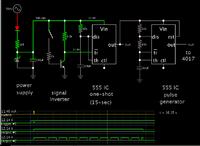
Here is a schematic that seems to work.


The AC power supply is rectified. It peaks at 21 or 22V. This is reduced to 12V by the zener diode.

The NPN inverts the switch signal. The 555's pin 2 is pulled low, to start the one-shot.

The one-shot provides 15 seconds of power to the pulse generator. There may be an alternate method of triggering, if you prefer to connect power directly to the 555 and 4017.
 
I've been modeling a little difference sequencer circuit for my doorbell. (See attached) Right now I am using some LEDs in place of the opticouplers for testing purposes. Before I go any further, I am having a little problem with the timing. When I start the sequence, the first output on the 4017 goes high for about 1 second while all the rest in sequence are about .75 seconds long. Does anyone have any ideas why they are not all consistent since they are all driven by the same 555 timer?
 

Attachments

  • Sequencer.jpg
    Sequencer.jpg
    96.8 KB · Views: 93

When I start the sequence, the first output on the 4017 goes high for about 1 second while all the rest in sequence are about .75 seconds long.

Yes, my simulation showed the same thing.

I believe it's because the capacitor starts from 0V. It takes an extra fraction of a second to charge up to the normal running level which is between 1/3 and 2/3 of the supply V.

Possible solutions:

(a) Ignore output #1 and start at output #2 on the 4017. This would cause a one second delay before the doorbell rings, and it may not be acceptable.

(b) Maintain capacitor charge at 1/3 of the supply V between uses. I'm not sure how to do this. It will require some ingenuity.

(c) Maintain cap charge at 2/3 of supply V between uses. This will shorten the output #1 time-On, so you could start at output #2 and there would be less of a delay.
 

I'm getting back to work on this circuit. I built it on a breadboard like the schematic in my previous post. The problem I'm having now is to a shorten the activation of the led (about .1 second) while the time between each led in the sequence is about 1 second. Right now, each led stays on until the next one comes on. Do I need to add another 555 some how to the led side of the circuit to flash each led in the sequence? Any ideas?
 

The problem I'm having now is to a shorten the activation of the led (about .1 second) while the time between each led in the sequence is about 1 second.

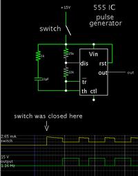
This innovation may do the job. Connect the capacitor to the top of the resistor network.
The pulses begin after a half-second delay. In effect this omits the longer initial pulse.
I added a resistor in line.
Screenshot:


Right now, each led stays on until the next one comes on. Do I need to add another 555 some how to the led side of the circuit to flash each led in the sequence? Any ideas?

Test whether each striker activates once and only once per application of power, then bounces back away from the chime.

I once worked on a type of door chimes which were activated by a metal rod being pulled through a solenoid. Inertia carried the rod through the solenoid, to strike the tube.
Afterward a spring pulled the rod back, away from the tube.

It was only at the first sudden burst of current through the solenoid, that the rod would strike the pipe. It did not strike any more times, no matter how long the pushbutton was held down.

If yours is similar then it should be okay for each of the 4017 outputs to be high for an entire second.
 
Status
Not open for further replies.

Part and Inventory Search

Welcome to EDABoard.com

Sponsor

Back
Top