unitt
Member level 1

- Joined
- Apr 2, 2013
- Messages
- 32
- Helped
- 0
- Reputation
- 0
- Reaction score
- 0
- Trophy points
- 1,286
- Activity points
- 1,518
Hi all,
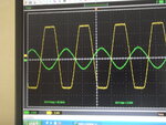
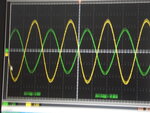
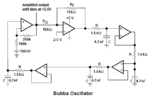
I have running a bubba sinus oscillator on 20Khz. The picture show the input and output singals. The quad opamp is a LME49740. I buffer the sinus wiht 2 voltage followers. The reason for this is that I will get a non-inverting and an inverting sinus.
And here goes it wrong and no idea how to get it.
I have much time spend wiht try-outs. but
every time no result.
Is here anyone who can explain what to do.
thank you.